166 Rockwell Automation Publication 1766-UM001I-EN-P - June 2015
Appendix A Specifications
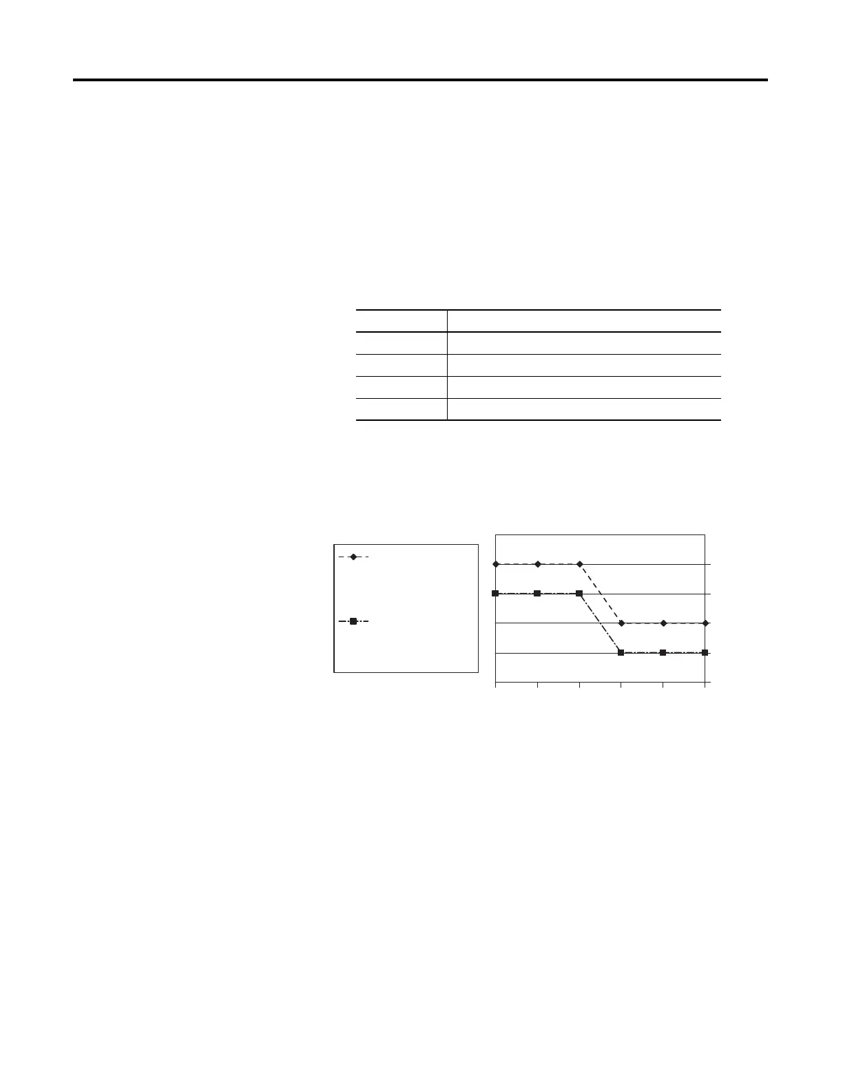
Relays Used vs. Maximum Current per Relay (24V DC) 1762-OX6I
(1) The continuous current per module must be limited so the module power does not exceed 1440VA.
(2) 6 A in ambient temperatures above 40 °C (104.°F)
(3) Surge Suppression – Connecting surge suppressors across your external inductive load will extend the life of
the relay contacts. For additional details, refer to Industrial Automation Wiring and Grounding Guidelines,
publication 1770-4.1.
(4) DC Make/Break Voltamperes must be limited to 50 VA for DC voltages between 28V DC and 125V DC. DC
Make/Break Voltamperes below 28V DC are limited by the 7 A Make/Break current limit.
Module Load Ratings 1762-OX6I
Volts (max.) Controlled Load (Current) per Module (max.)
240V AC 6 A
120V AC 12 A
(1)
(1) Current per relay limited to 6 A at ambient temperatures above 40 °C (104.°F).
125V DC 11.5 A
24V DC 30 A
(2)
(2) 24 A in ambient temperatures above 40 °C (104.°F). Limited by ambient temperature
and the number of relays controlling loads. See below.
Number of Relays Controlling Loads
Maximum Current per Relay (Amps)
Ambient Temperature
below 40 °C (104.°F)
Ambient Temperature
above 40 °C (104.°F)

 Loading...


