EasyManuals Logo

Allen-Bradley MicroLogix 1400 User Manual

Allen-Bradley MicroLogix 1400
404 pages
To Next Page IconTo Next Page
To Previous Page IconTo Previous Page
Page #215 background imageLoading...
Page #215 background image
Rockwell Automation Publication 1766-UM001I-EN-P - June 2015 201
Using ControlFLASH to Upgrade Your Operating System Appendix D
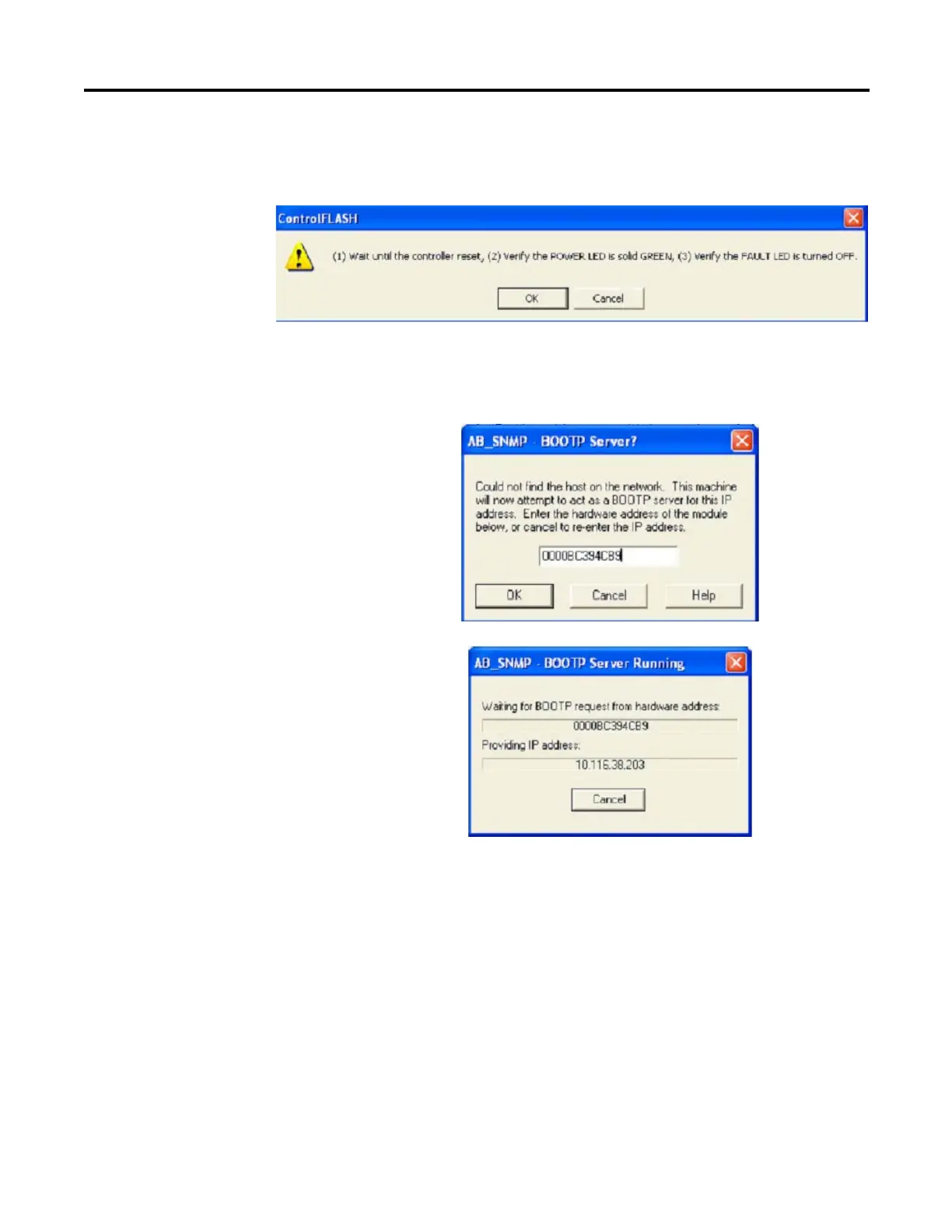
15. After the flashing is complete, the following dialog box prompts you to
wait for the controller to reset, verify that the POWER LED is solid
GREEN and verify the FAULT LED is turned OFF.
16. Click the OK button.
17. Enter the hardware address if prompted. Otherwise, the AB_SNMP -
BOOTP Server Running dialog box may appear.
If the AB_SNMP - BOOTP Server Running dialog box appears and if
there is no response from the controller for more than 30 seconds, click
Cancel.

Table of Contents

Other manuals for Allen-Bradley MicroLogix 1400

Questions and Answers:

Question and Answer IconNeed help?

Do you have a question about the Allen-Bradley MicroLogix 1400 and is the answer not in the manual?

Allen-Bradley MicroLogix 1400 Specifications

General IconGeneral
Processor32-bit
Expansion ModulesUp to 7 expansion I/O modules
Power Supply24V DC or 120/240V AC
Programming SoftwareRSLogix 500
Communication PortsEthernet, RS-232/RS-485 combo port
Controller TypeProgrammable Logic Controller (PLC)
SeriesMicroLogix
Digital Outputs12
Analog Inputs6 (embedded)
Analog Outputs2 (embedded)
High-Speed Counter6 high-speed counters
Pulse Output2 (embedded)
Ethernet PortYes

Related product manuals