EasyManuals Logo

Allen-Bradley MicroLogix 1400 User Manual

Allen-Bradley MicroLogix 1400
404 pages
To Next Page IconTo Next Page
To Previous Page IconTo Previous Page
Page #216 background imageLoading...
Page #216 background image
202 Rockwell Automation Publication 1766-UM001I-EN-P - June 2015
Appendix D Using ControlFLASH to Upgrade Your Operating System
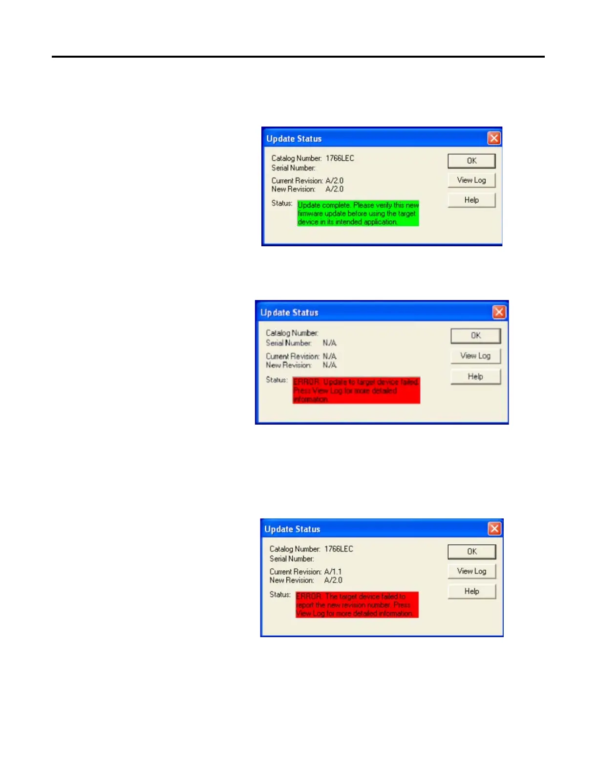
The Update Status dialog box is displayed. If the update was successful, the
status text box is green and has an appropriate message.
If the update was not successful, the status text box is red and has an
appropriate message.
If the following dialog box appears, it indicates that the controller ended
up in a Missing/Corrupt OS state. The current revision number reflects
the version of Boot Firmware.
To recover the controller from this state, see Recovering from Missing or
Corrupt OS State on page 206.

Table of Contents

Other manuals for Allen-Bradley MicroLogix 1400

Questions and Answers:

Question and Answer IconNeed help?

Do you have a question about the Allen-Bradley MicroLogix 1400 and is the answer not in the manual?

Allen-Bradley MicroLogix 1400 Specifications

General IconGeneral
Processor32-bit
Expansion ModulesUp to 7 expansion I/O modules
Power Supply24V DC or 120/240V AC
Programming SoftwareRSLogix 500
Communication PortsEthernet, RS-232/RS-485 combo port
Controller TypeProgrammable Logic Controller (PLC)
SeriesMicroLogix
Digital Outputs12
Analog Inputs6 (embedded)
Analog Outputs2 (embedded)
High-Speed Counter6 high-speed counters
Pulse Output2 (embedded)
Ethernet PortYes

Related product manuals