300 Rockwell Automation Publication 1766-UM001I-EN-P - June 2015
Appendix F MicroLogix 1400 Distributed Network Protocol (DNP3)
227 Read Only INT 1 1 Support for counter events 1
228 Read Only UINT 4 2 Max counter index 256*2
229 Read Only UINT 4 2 Number of counter points 0…256*2
230 Read Only INT 1 1 Support for frozen analog
inputs
0
231 Read Only INT 1 1 Support for analog input
events
1
232 Read Only UINT 4 2 Maximum analog input index 256*3
233 Read Only UINT 4 2 Number of analog input
points
0…256*3
234 Read Only INT 1 1 Support for double-bit binary
input events
1
235 Read Only UINT 4 2 Maximum double-bit binary
input index
256*8
236 Read Only UINT 4 2 Number of double-bit binary
input points
0…256*8
237 Read Only INT 1 1 Support for binary input
events
1
238 Read Only UINT 4 2 Max binary input index 256*16
239 Read Only UINT 4 2 Number of binary input
points
0…256*16
240 Read Only UINT 4 2 Max transmit fragment size 2048 (27…2048). When this value is written
to the controller, the communication
configuration file is changed to this value.
241 Read Only UINT 4 2 Max receive fragment size 2048
242 Read Only VSTR length of the
string value
length of the
string value
Device manufacturer's
software version
This variation returns firmware FRN. "FRN
1.00".
Supported ranges: "FRN x.yy", "FRN x.yyy",
"FRN xx.yy" or "FRN xx.yyy" where x, xx is 0 ~
99 and yy, yyy 00 ~ 999.
For example, "FRN 1.00", "FRN 1.05", "FRN
12.05", "FRN 102.27" or "FRN 103.117".
243 Read Only VSTR length of the
string value
length of the
string value
Device manufacturer's
hardware version
This variation returns
hardware series and
revision of the
controller. "HW SER
A/REV 01".
This variation returns
hardware series and
revision of the
controller. "HW SER
A/REV 03".
Supported ranges: "HW SER x/REV yy" where
x is A ~ F and yy is 00 ~ 31.
For example, "HW SER A/REV 01", "HW SER
B/REV 03", or "HW SER C/REV 31".
244 - - - - Reserved for future
assignment
--
245 Read
/Write
VSTR length of the
string value,
max 255
bytes
length of the
string value,
max 255
bytes
User-assigned location name "". Non-NULL terminated.
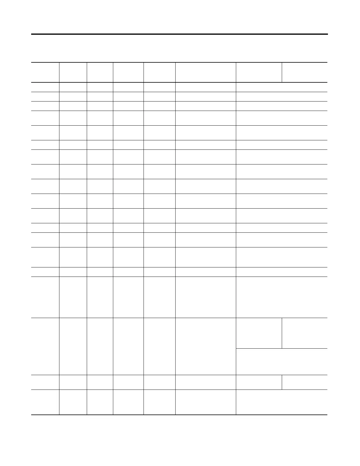
Object Group 0, Variations for Attribute Set 0
Variation Read
/Write
Attribute
Data Type
Length in
Bytes
(Series A)
Max Length
in Bytes
(Series B)
Description Value (Series A) Value (Series B)

 Loading...


