Rockwell Automation Publication 1766-UM001I-EN-P - June 2015 35
Wire Your Controller Chapter 3
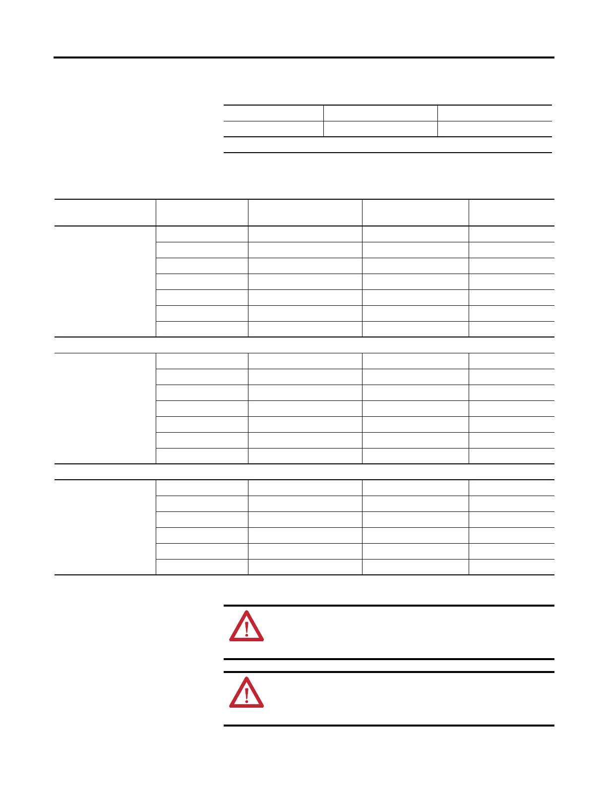
Solid wire Cu-90⋅C (194⋅F) 14…22 AWG
Stranded wire Cu-90⋅C (194⋅F) 16…22 AWG
Wiring torque = 0.791Nm (7 in-lb) rated.
Wire Types and Sizes
Output Terminal Grouping
Controllers Output Group Description
Outputs
Voltage Terminal
Output Terminal
1766-L32BWA
1766--L32BWAA
Group 0 Isolated relay output VAC/DC0 OUT 0
Group 1 Isolated relay output VAC/DC1 OUT 1
Group 2 Isolated relay output VAC/DC2 OUT 2
Group 3 Isolated relay output VAC/DC3 OUT 3
Group 4 Isolated relay output VAC/DC4 OUT 4, OUT 5
Group 5 Isolated relay output VAC/DC5 OUT 6, OUT 7
Group 6 Isolated relay output VAC/DC6 OUT 8…11
1766-L32AWA
1766-L32AWAA
Group 0 Isolated relay output VAC/DC0 OUT 0
Group 1 Isolated relay output VAC/DC1 OUT 1
Group 2 Isolated relay output VAC/DC2 OUT 2
Group 3 Isolated relay output VAC/DC3 OUT 3
Group 4 Isolated relay output VAC/DC4 OUT 4, OUT 5
Group 5 Isolated relay output VAC/DC5 OUT 6, OUT 7
Group 6 Isolated relay output VAC/DC6 OUT 8…11
1766-L32BXB
1766-L32BXBA
Group 0 Isolated relay output VAC/DC0 OUT 0
Group 1 Isolated relay output VAC/DC1 OUT 1
Group 2 FET output VDC2/COM 2 OUT 2…7
Group 3 Isolated relay output VAC/DC3 OUT 8
Group 4 Isolated relay output VAC/DC4 OUT 9
Group 5 Isolated relay output VAC/DC5 OUT 10, OUT 11
WARNING: If you connect or disconnect wiring while the
field-side power is on, an electrical arc can occur. This could cause
an explosion in hazardous location installations. Be sure that
power is removed or the area is nonhazardous before proceeding.
WARNING: The local programming terminal port is intended for
temporary use only and must not be connected or disconnected
unless the area is free of ignitable concentrations of flammable
gases or vapors.

 Loading...


