66 Rockwell Automation Publication 1766-UM001I-EN-P - June 2015
Chapter 4 Communication Connections
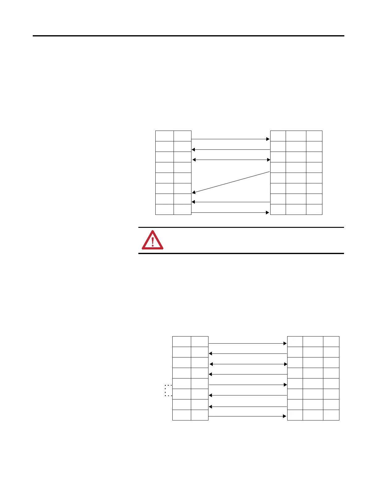
MicroLogix 1400 Channel 0 to Modem Cable Pinout
When connecting MicroLogix 1400 Channel 0 to a modem using an RS-232
cable, the maximum that the cable length may be extended is 15.24 m (50 ft).
Constructing Your Own Modem Cable
If you construct your own modem cable, the maximum cable length is 15.24 m
(50 ft) with a 25-pin or 9-pin connector. Refer to the following typical pinout for
constructing a straight-through cable:
ATTENTION: Do not connect pins 1 and 8. This connection will
cause damage to the RS-232/485 communication port (channel 0)
of the MicroLogix 1400 and/or the controller itself.
DTE Device
(MicroLogix
1400
Channel 0)
DCE Device
(Modem,
PanelView,
etc.)
8-Pin 25-Pin 9-Pin
7 TXD TXD 2 3
4 RXD RXD 3 2
2GND GND7 5
1B(+) DCD8 1
8A(-) DTR204
5 DCD DSR 6 6
6 CTS CTS 5 8
3 RTS RTS 4 7
AIC+ Optical Isolator
or 1766-LEC Channel 2
Modem
9-Pin 25-Pin 9-Pin
3 TXD TXD 2 3
2 RXD RXD 3 2
5GND GND7 5
1CD CD8 1
4DTR DTR204
6 DSR DSR 6 6
8 CTS CTS 5 8
7 RTS RTS 4 7
pins 4 and 6
are internally
connected for
1766-LEC only

 Loading...


