EasyManuals Logo

Allen-Bradley PowerFlex 40 User Manual

Allen-Bradley PowerFlex 40
218 pages
To Next Page IconTo Next Page
To Previous Page IconTo Previous Page
Page #111 background imageLoading...
Page #111 background image
Publication IASIMP-QS001C-EN-P - October 2009 111
Create a Project Using RSLogix 5000 Programming Software Chapter 10
Add the 1769-SDN to the Project
DeviceNet only
3. In the Name field, type a
name for your SDN module.
4. In the Slot field, enter the
Slot number.
There can be a maximum of three modules between
the 1769-SDN
module and the power supply.
5. In the Input Size and Output Size fields, enter values to accommodate the input and
output sizes of the modules in your system.
This example uses 20.
For more information about determining input and output sizes, see the DeviceNet
Modules in Logix5000 Control Systems User Manual, publication DNET-UM004
.
6. From the Electronic Keying pull-down, choose Disable Keying.
7. Check the Open Module Properties check box and click OK.
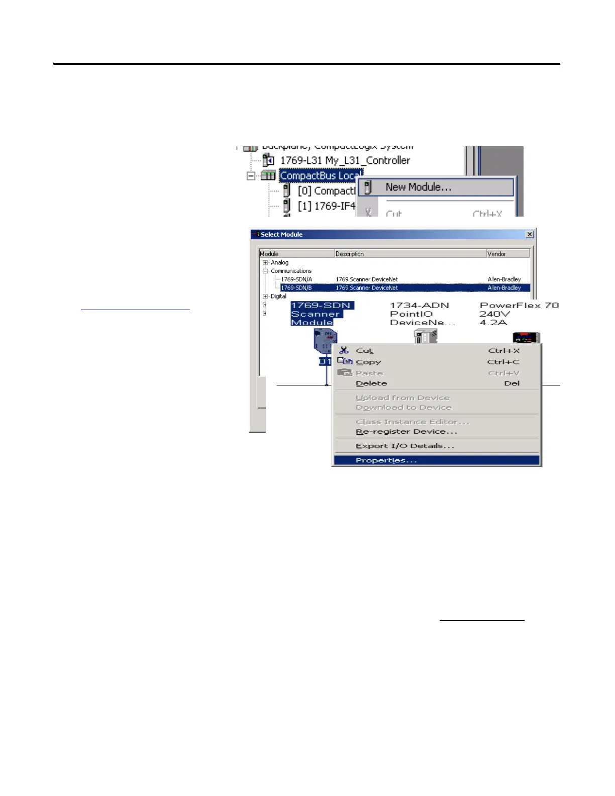
1. Right-click CompactBus
Local and select New
Module.
2. Under Communications,
select 1769-SDN with the
series letter recorded on the
Network Worksheet
and click
OK.

Table of Contents

Other manuals for Allen-Bradley PowerFlex 40

Questions and Answers:

Question and Answer IconNeed help?

Do you have a question about the Allen-Bradley PowerFlex 40 and is the answer not in the manual?

Allen-Bradley PowerFlex 40 Specifications

General IconGeneral
Output Voltage0 to Input Voltage
EnclosureIP20
Control MethodV/Hz, Sensorless Vector Control
CommunicationRS485
Frequency0 to 400 Hz
ProtectionOverload, Overvoltage, Undervoltage, Short Circuit
Operating Temperature-10 to 50°C (14 to 122°F)
Storage Temperature-40...70 °C (-40...158 °F)
Humidity5% to 95% non-condensing
Input Voltage200-240V AC, 380-480V AC, 500-600V AC (depending on model)

Related product manuals