EasyManuals Logo

Allen-Bradley PowerFlex 40 User Manual

Allen-Bradley PowerFlex 40
218 pages
To Next Page IconTo Next Page
To Previous Page IconTo Previous Page
Page #67 background imageLoading...
Page #67 background image
Publication IASIMP-QS001C-EN-P - October 2009 67
Prepare the PowerFlex 40 Drive Chapter 5
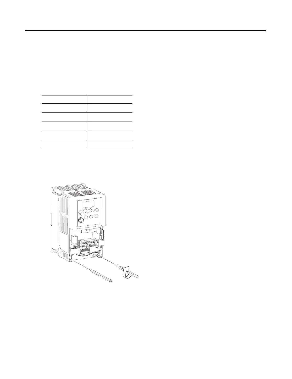
Connect the Communication Adapter to the PowerFlex 40 Drive
22-COMM-E, 22-COMM-C, 22-COMM-D adapter
1. If you are using a DeviceNet network, remove the terminal block connector from the
22-COMM-D adapter and connect the DeviceNet cable to the terminal block.
2. For all adapters, attach the extending screws.
Connect To
Red V+
White CAN High
Bare Shield
Blue CAN Low
Black V-
0.8…1 Nm (7…9 lb•in)

Table of Contents

Other manuals for Allen-Bradley PowerFlex 40

Questions and Answers:

Question and Answer IconNeed help?

Do you have a question about the Allen-Bradley PowerFlex 40 and is the answer not in the manual?

Allen-Bradley PowerFlex 40 Specifications

General IconGeneral
Output Voltage0 to Input Voltage
EnclosureIP20
Control MethodV/Hz, Sensorless Vector Control
CommunicationRS485
Frequency0 to 400 Hz
ProtectionOverload, Overvoltage, Undervoltage, Short Circuit
Operating Temperature-10 to 50°C (14 to 122°F)
Storage Temperature-40...70 °C (-40...158 °F)
Humidity5% to 95% non-condensing
Input Voltage200-240V AC, 380-480V AC, 500-600V AC (depending on model)

Related product manuals