EasyManuals Logo

Allen-Bradley PowerFlex 40 User Manual

Allen-Bradley PowerFlex 40
218 pages
To Next Page IconTo Next Page
To Previous Page IconTo Previous Page
Page #127 background imageLoading...
Page #127 background image
Publication IASIMP-QS001C-EN-P - October 2009 127
Add Distributed I/O Modules to the Project Chapter 11
Add Ladder Logic
EtherNet/IP and ControlNet only
(for a DeviceNet, go to page 129
)
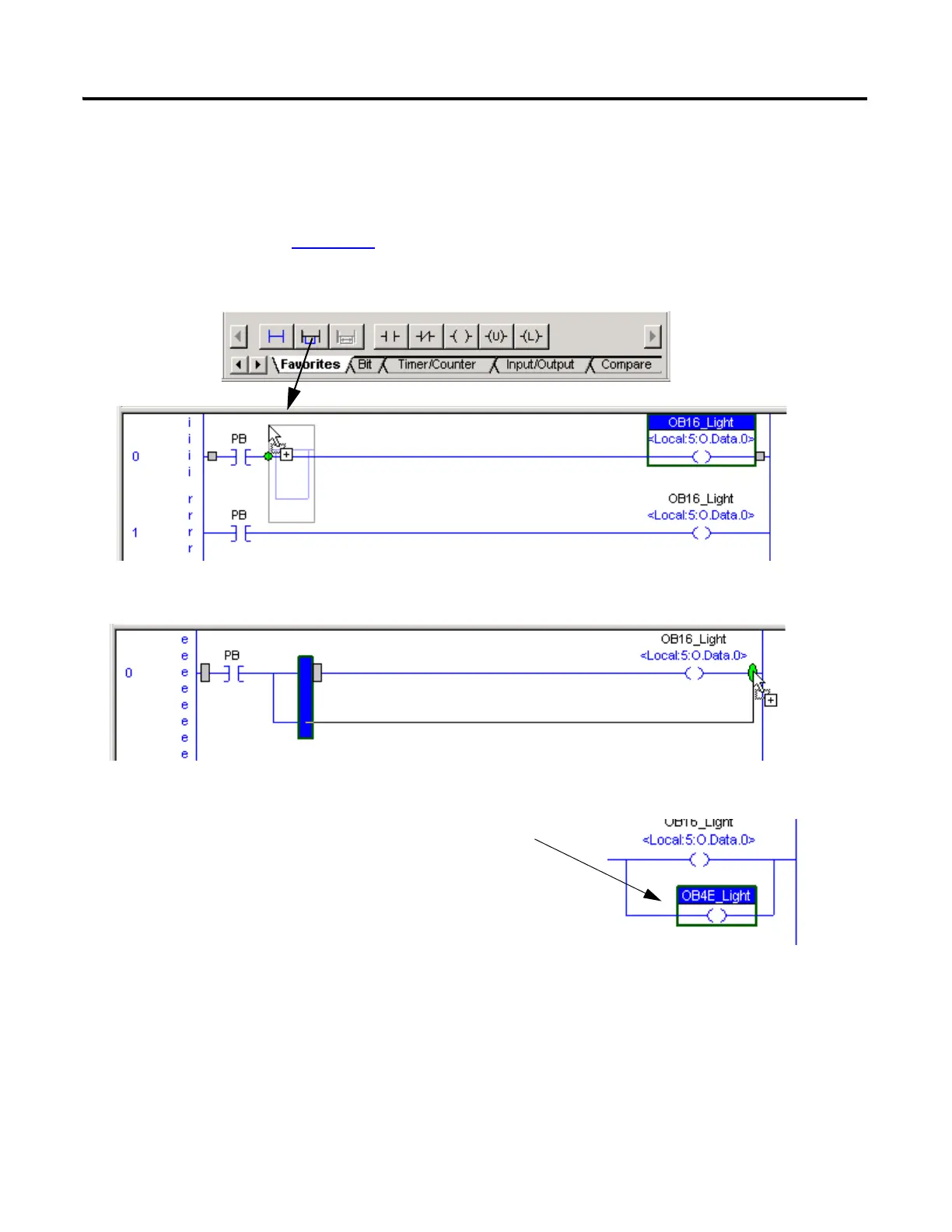
1. In RSLogix 5000 programming software, drag and drop a Branch onto the rung.
2. Expand the branch to the right side of the xxxx_Light.
3. Drag and drop another Output Energize element
onto the Branch and name it xxxx_Light
(where xxxx is the suffix of the catalog number of
the digital 1734 POINT output module).

Table of Contents

Other manuals for Allen-Bradley PowerFlex 40

Questions and Answers:

Question and Answer IconNeed help?

Do you have a question about the Allen-Bradley PowerFlex 40 and is the answer not in the manual?

Allen-Bradley PowerFlex 40 Specifications

General IconGeneral
Output Voltage0 to Input Voltage
EnclosureIP20
Control MethodV/Hz, Sensorless Vector Control
CommunicationRS485
Frequency0 to 400 Hz
ProtectionOverload, Overvoltage, Undervoltage, Short Circuit
Operating Temperature-10 to 50°C (14 to 122°F)
Storage Temperature-40...70 °C (-40...158 °F)
Humidity5% to 95% non-condensing
Input Voltage200-240V AC, 380-480V AC, 500-600V AC (depending on model)

Related product manuals