EasyManuals Logo

Allen-Bradley PowerFlex 40 User Manual

Allen-Bradley PowerFlex 40
218 pages
To Next Page IconTo Next Page
To Previous Page IconTo Previous Page
Page #22 background imageLoading...
Page #22 background image
22 Publication IASIMP-QS001C-EN-P - October 2009
Chapter 1 Prepare the CompactLogix Hardware
Make Network Connections
1769-L32E or 1769-L35E controllers
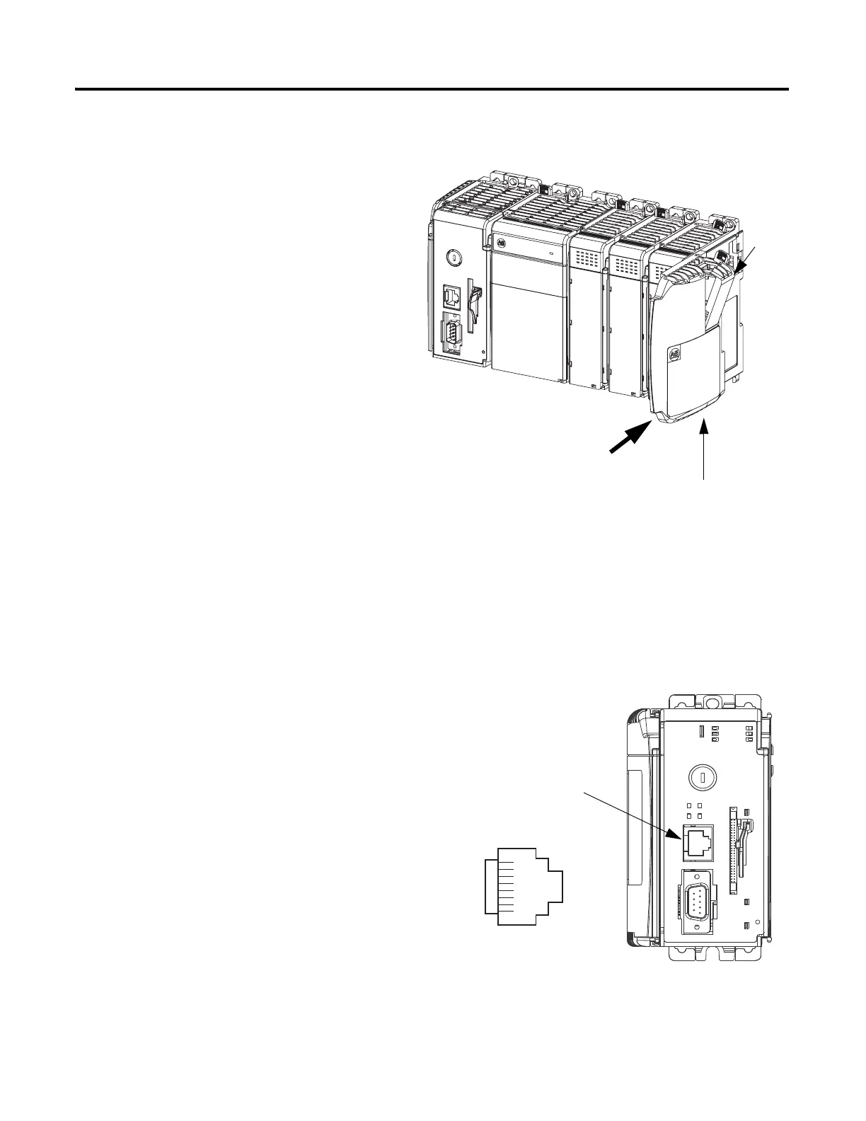
5. Lock all of the locking tabs on the top
of the modules.
6. Verify that the tabs are all the way to the
left.
7. Slide the end cap terminator on and
lock the locking tab.
8. Press the assembled system onto a DIN
rail.
Locking
Tab
End-cap Terminator
8 ------ NC
7 ------ NC
6 ------ RD-
5 ------ NC
4 ------ NC
3 ------ RD+
2 ------ TD-
1 ------ TD+
1. Insert an Ethernet cable with an RJ-45
connector.
2. Connect the other end of the cable to an
Ethernet switch
.
Ethernet Port

Table of Contents

Other manuals for Allen-Bradley PowerFlex 40

Questions and Answers:

Question and Answer IconNeed help?

Do you have a question about the Allen-Bradley PowerFlex 40 and is the answer not in the manual?

Allen-Bradley PowerFlex 40 Specifications

General IconGeneral
Output Voltage0 to Input Voltage
EnclosureIP20
Control MethodV/Hz, Sensorless Vector Control
CommunicationRS485
Frequency0 to 400 Hz
ProtectionOverload, Overvoltage, Undervoltage, Short Circuit
Operating Temperature-10 to 50°C (14 to 122°F)
Storage Temperature-40...70 °C (-40...158 °F)
Humidity5% to 95% non-condensing
Input Voltage200-240V AC, 380-480V AC, 500-600V AC (depending on model)

Related product manuals