EasyManuals Logo

Allen-Bradley PowerFlex 40 User Manual

Allen-Bradley PowerFlex 40
218 pages
To Next Page IconTo Next Page
To Previous Page IconTo Previous Page
Page #51 background imageLoading...
Page #51 background image
Publication IASIMP-QS001C-EN-P - October 2009 51
Prepare the Distributed POINT I/O Hardware Chapter 3
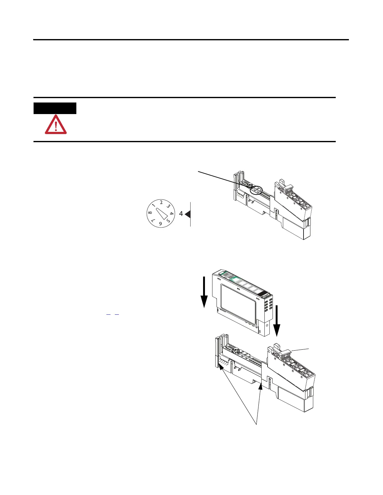
Mount the POINT I/O Modules
All controllers, POINT I/O modules, and wiring bases
1. Using a small, flathead screwdriver, rotate the
keyswitch to match the figure on the I/O
module.
2. Press the module into the wiring base.
3. Snap the handle up.
4. Complete steps 1
3 with all POINT I/O
modules.
5. Slide the first module and wiring base
assembly along the adapter and press it
onto the DIN rail.
6. Repeat with all of the I/O assemblies.
Handle
Tongue-and-groove Slots
The 1734-IT2I module must be mounted in the 1734-TBCJC wiring base. All other modules can be
mounted in either of the 1734-TB or 1734-TBS wiring bases.
Figure on Module
Wiring Base
Module

Table of Contents

Other manuals for Allen-Bradley PowerFlex 40

Questions and Answers:

Question and Answer IconNeed help?

Do you have a question about the Allen-Bradley PowerFlex 40 and is the answer not in the manual?

Allen-Bradley PowerFlex 40 Specifications

General IconGeneral
Output Voltage0 to Input Voltage
EnclosureIP20
Control MethodV/Hz, Sensorless Vector Control
CommunicationRS485
Frequency0 to 400 Hz
ProtectionOverload, Overvoltage, Undervoltage, Short Circuit
Operating Temperature-10 to 50°C (14 to 122°F)
Storage Temperature-40...70 °C (-40...158 °F)
Humidity5% to 95% non-condensing
Input Voltage200-240V AC, 380-480V AC, 500-600V AC (depending on model)

Related product manuals