Publication IASIMP-QS001C-EN-P - October 2009 65
Prepare the PowerFlex 40 Drive Chapter 5
Mount the PowerFlex 40 Drive
For mounting instructions, see the PowerFlex 40 Drive User Manual, publication
22B-UM001
.
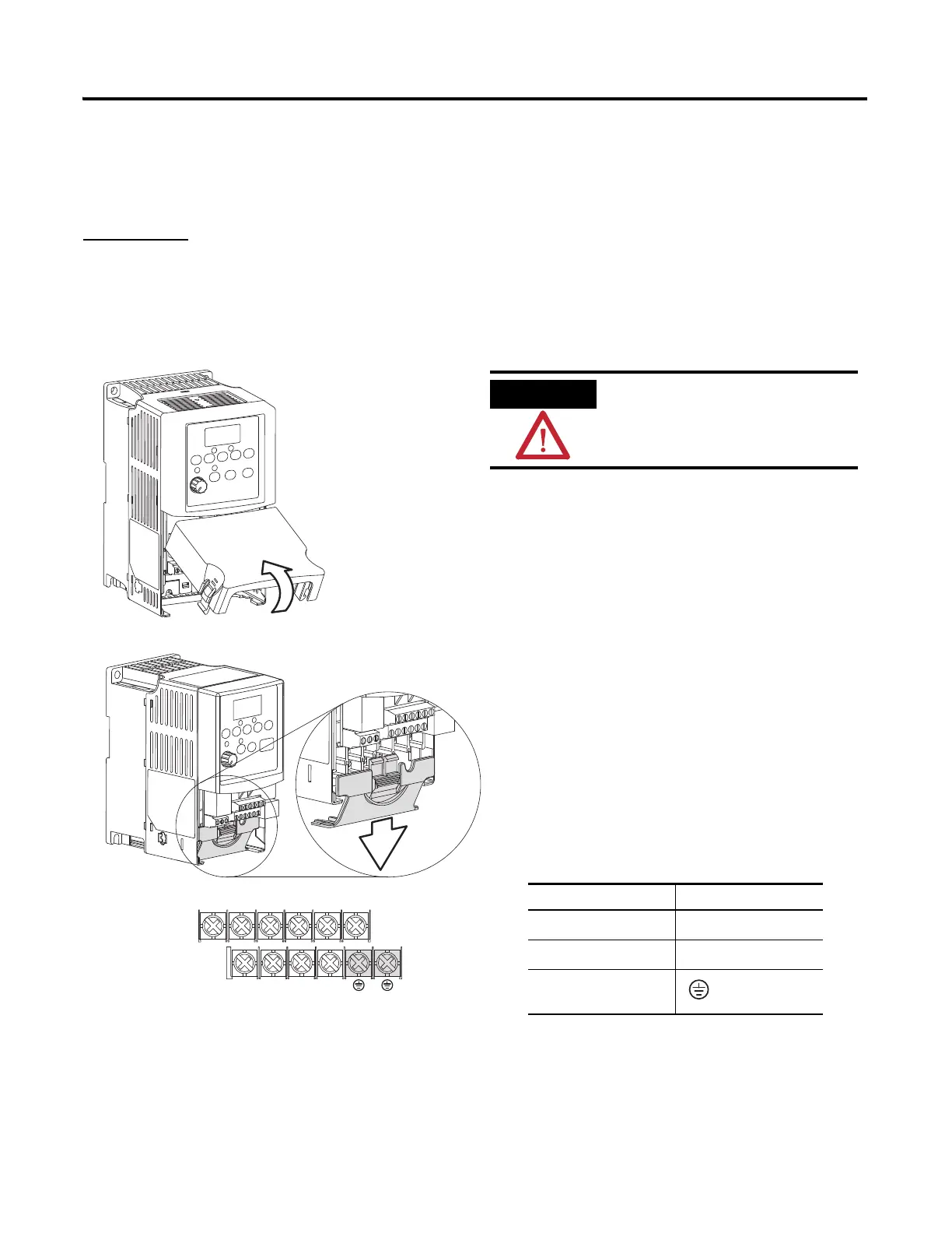
Wire Power
V/T2T/L3S/L2R/L1 U/T1 W/T3
BR+ BR-DC- DC+
2. Remove the terminal block cover to
access the power connections.
3. Insert the 120/240V AC, V AC COM
and chassis ground wires and tighten
the terminal screws.
Connect To
120/240V AC
R/L1
V AC COM
S/L2
Chassis ground
Verify that all incoming power
is turned off before wiring
power.

 Loading...


