EasyManuals Logo

Allen-Bradley PowerFlex 40 User Manual

Allen-Bradley PowerFlex 40
218 pages
To Next Page IconTo Next Page
To Previous Page IconTo Previous Page
Page #4 background imageLoading...
Page #4 background image
4 Publication IASIMP-QS001C-EN-P - October 2009
Where to Start
How Hardware is Connected
This quick start demonstrates the following possible control systems. Choose your hardware
and networks, then follow the matching examples.
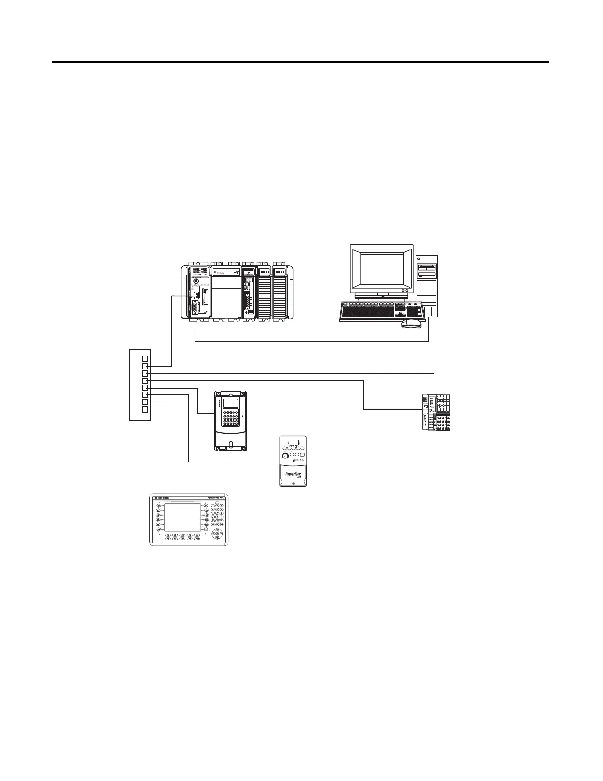
Option 1: 1769-L32E, 1769-L35E Control System
PanelView Plus terminal
with built-in EtherNet/IP
Ethernet
Switch
1769-L32E or 1769-L35E
with Optional 1769-SDN for the
DeviceNet Network
Serial (CP3 Cable)
PowerFlex 70 Drive
with 20-COMM-E
PowerFlex 40 Drive
with 22-COMM-E
PanelView Plus Terminal
with Built-in EtherNet/IP
Port
Computer with
Standard Ethernet Port
Distributed
POINT I/O
Modules with
1734-AENT

Table of Contents

Other manuals for Allen-Bradley PowerFlex 40

Questions and Answers:

Question and Answer IconNeed help?

Do you have a question about the Allen-Bradley PowerFlex 40 and is the answer not in the manual?

Allen-Bradley PowerFlex 40 Specifications

General IconGeneral
Output Voltage0 to Input Voltage
EnclosureIP20
Control MethodV/Hz, Sensorless Vector Control
CommunicationRS485
Frequency0 to 400 Hz
ProtectionOverload, Overvoltage, Undervoltage, Short Circuit
Operating Temperature-10 to 50°C (14 to 122°F)
Storage Temperature-40...70 °C (-40...158 °F)
Humidity5% to 95% non-condensing
Input Voltage200-240V AC, 380-480V AC, 500-600V AC (depending on model)

Related product manuals