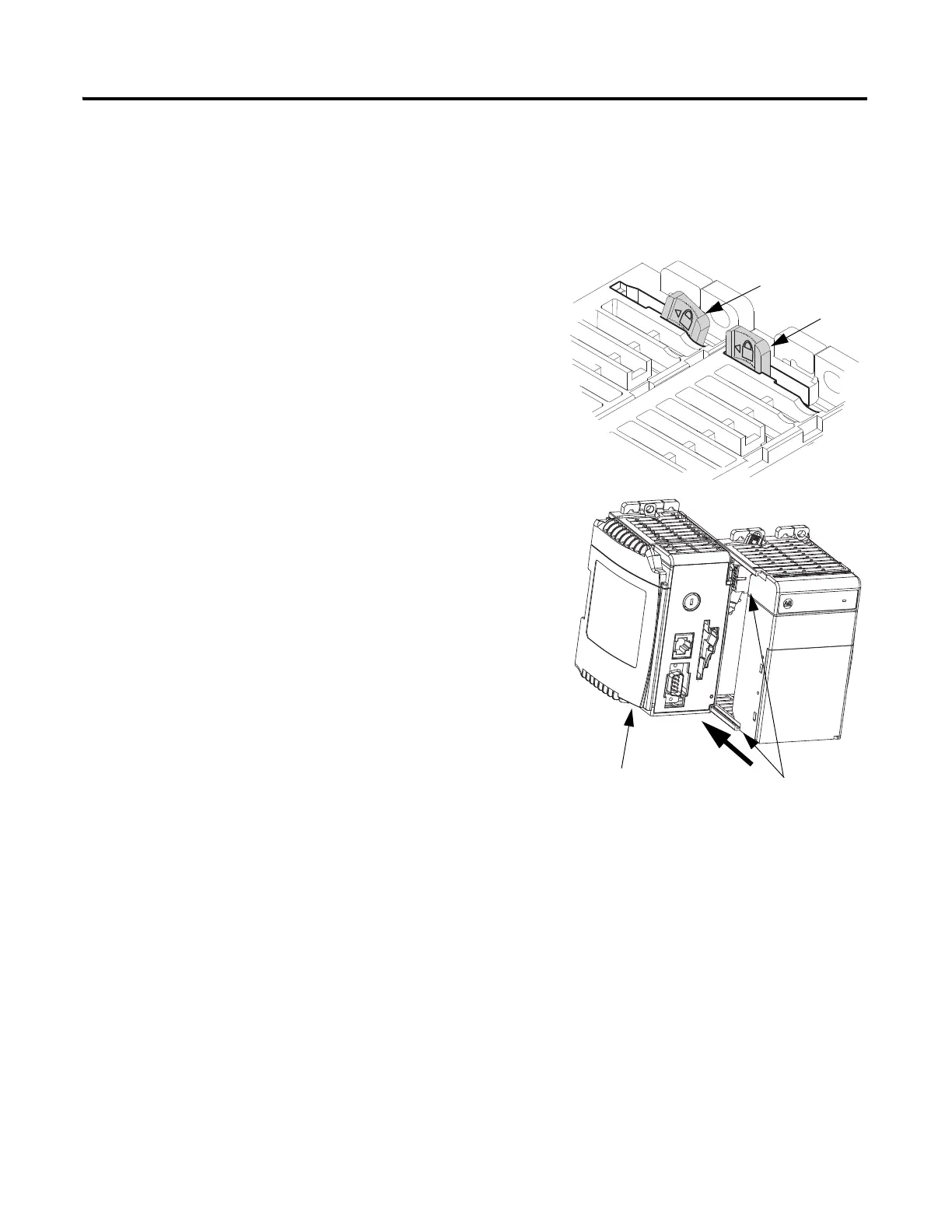
EasyManuals Logo

Allen-Bradley PowerFlex 40 User Manual

Allen-Bradley PowerFlex 40
218 pages
To Next Page IconTo Next Page
To Previous Page IconTo Previous Page
Page #21 background imageLoading...
Page #21 background image
Publication IASIMP-QS001C-EN-P - October 2009 21
Prepare the CompactLogix Hardware Chapter 1
Assemble the System
Controller, power supply, local I/O modules, 1769-SDN module, end cap terminator
Unlocked
Locked
Tongue-and-groove Slots
1. On the top of each module, verify that all of the
locking tabs are unlocked.
2. Use the tongue-and-groove slots to slide the
power supply, then the I/O modules onto the
controller.
3. If you have an 1769-SDN module, record the
series letter (see label on the side of the module)
on the Network Worksheet inside the back cover
of this quick start.
4. If you have an 1769-SDN module, slide it onto
the other modules.
There can be a maximum of three modules
between the 1769-SDN module and the power
supply.
Controller

Table of Contents

Other manuals for Allen-Bradley PowerFlex 40

Questions and Answers:

Question and Answer IconNeed help?

Do you have a question about the Allen-Bradley PowerFlex 40 and is the answer not in the manual?

Allen-Bradley PowerFlex 40 Specifications

General IconGeneral
Output Voltage0 to Input Voltage
EnclosureIP20
Control MethodV/Hz, Sensorless Vector Control
CommunicationRS485
Frequency0 to 400 Hz
ProtectionOverload, Overvoltage, Undervoltage, Short Circuit
Operating Temperature-10 to 50°C (14 to 122°F)
Storage Temperature-40...70 °C (-40...158 °F)
Humidity5% to 95% non-condensing
Input Voltage200-240V AC, 380-480V AC, 500-600V AC (depending on model)

Related product manuals