Publication IASIMP-QS001C-EN-P - October 2009 93
Configure the DeviceNet Network Chapter 9
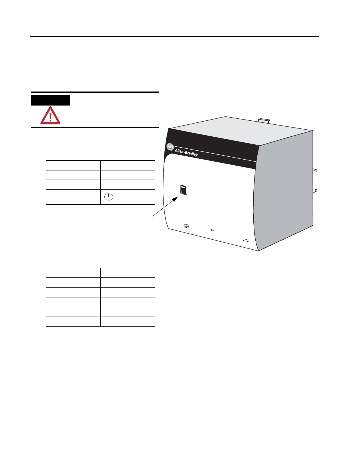
Apply Power to the DeviceNet Network
1606-XLDNET8 power supply
Input
AC 100-120/200-240V
N L
Isolate power before disconnecting
1606-XL
POWER SUPPLY
DC ok
Output
200W Limited Power
DC 24V / 8A
+ –
DC ok
AC 120V
AC 240V
1. Connect incoming power to the
power supply.
2. Place the switch in the position that
matches your supply voltage.
3. Connect the DeviceNet power tap
to the power supply.
For this example, there is no need to connect the DC ok relay on the power supply to
anything.
4. If you have unused DeviceNet wires, make sure they do not come into contact with
the other wires.
5. Connect the DeviceNet power tap to the DeviceNet network.
6. Turn on incoming power.
Verify that all incoming
power is turned off before
wiring power.
Connect To
V AC COM N (neutral)
120/240V AC L (line)
Ground
Connect To
Red +
White N/A
Shield N/A
Blue N/A
Black –

 Loading...


