EasyManuals Logo

Allen-Bradley PowerFlex 40 User Manual

Allen-Bradley PowerFlex 40
218 pages
To Next Page IconTo Next Page
To Previous Page IconTo Previous Page
Page #59 background imageLoading...
Page #59 background image
Publication IASIMP-QS001C-EN-P - October 2009 59
Prepare the PowerFlex 70 Drive Chapter 4
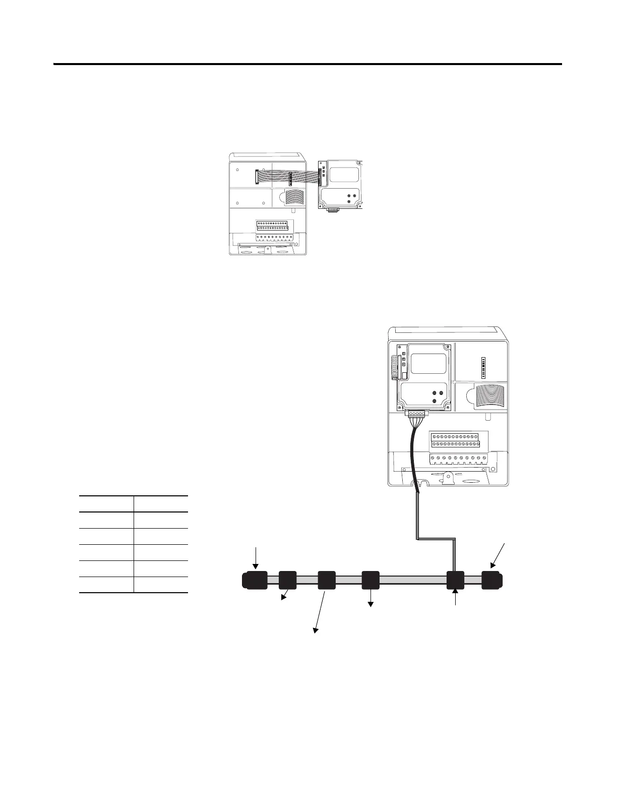
Connect Communication Adapter to the PowerFlex 70 Drive
20-COMM-D DeviceNet Adapter for DeviceNet System
1. Connect the flat-ribbon
cable between the adapter
and the PowerFlex 70
drive.
2. Fold the cable under
adapter without creasing
and secure adapter on
drive using the captive
screws.
3. Remove a knockout from
the bottom plate on the
drive and route the
DeviceNet network cable
through the hole.
4. Wire the KwikLink QD
Micro Cordset to the
20-COMM-D connector.
5. Connect the QD Micro
Cordset to a KwikLink
sealed micro connector
on the DeviceNet
network.
6. Replace drive cover.
Connect To
Red V+
White CAN High
Bare Shield
Blue CAN Low
Black V-
POINT I/O with
1734-ADN Adapter
KwikLink Sealed
Terminator
KwikLink Sealed
Terminator
KwikLink Sealed
Micro Connector
1606-XLDNET8
Power Supply
1769-SDN
DeviceNet Module

Table of Contents

Other manuals for Allen-Bradley PowerFlex 40

Questions and Answers:

Question and Answer IconNeed help?

Do you have a question about the Allen-Bradley PowerFlex 40 and is the answer not in the manual?

Allen-Bradley PowerFlex 40 Specifications

General IconGeneral
Output Voltage0 to Input Voltage
EnclosureIP20
Control MethodV/Hz, Sensorless Vector Control
CommunicationRS485
Frequency0 to 400 Hz
ProtectionOverload, Overvoltage, Undervoltage, Short Circuit
Operating Temperature-10 to 50°C (14 to 122°F)
Storage Temperature-40...70 °C (-40...158 °F)
Humidity5% to 95% non-condensing
Input Voltage200-240V AC, 380-480V AC, 500-600V AC (depending on model)

Related product manuals