EasyManuals Logo

Allen-Bradley PowerFlex 40 User Manual

Allen-Bradley PowerFlex 40
218 pages
To Next Page IconTo Next Page
To Previous Page IconTo Previous Page
Page #52 background imageLoading...
Page #52 background image
52 Publication IASIMP-QS001C-EN-P - October 2009
Chapter 3 Prepare the Distributed POINT I/O Hardware
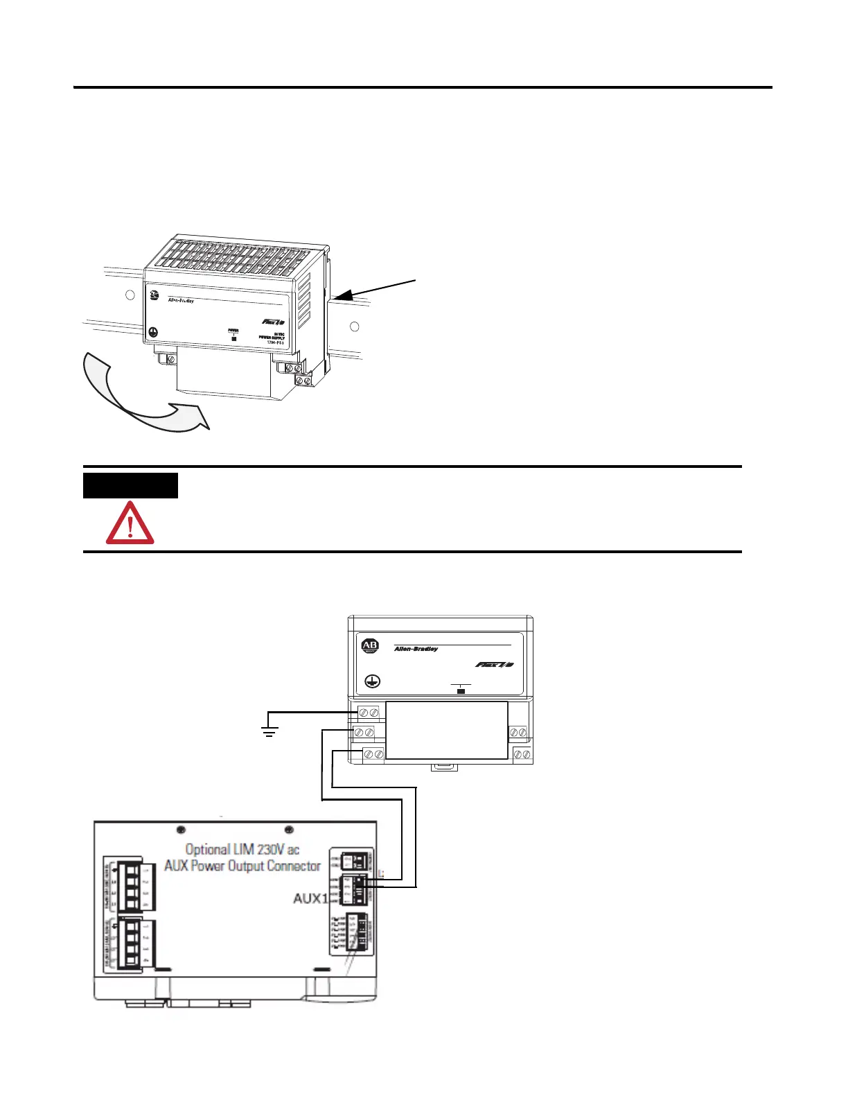
Mount and Wire the POINT I/O Power Supply
1794-PS3 or 1794-PS13 power supplies
1. Hook the upper-lip of the DIN rail latch onto the
DIN rail.
2. Press the module onto the DIN rail.
3. Connect the
120/230V AC
power, 120/230V
AC common and
AC Ground wires.
Verify that all incoming power is turned off before wiring power.
Upper-lip of DIN rail latch.
r
ewo
P
CD
V42
YLPPUS REWO
P
3S
P-4971
V42
MO
C
GR
L2/N
L1
L2
L1
Top View

Table of Contents

Other manuals for Allen-Bradley PowerFlex 40

Questions and Answers:

Question and Answer IconNeed help?

Do you have a question about the Allen-Bradley PowerFlex 40 and is the answer not in the manual?

Allen-Bradley PowerFlex 40 Specifications

General IconGeneral
Output Voltage0 to Input Voltage
EnclosureIP20
Control MethodV/Hz, Sensorless Vector Control
CommunicationRS485
Frequency0 to 400 Hz
ProtectionOverload, Overvoltage, Undervoltage, Short Circuit
Operating Temperature-10 to 50°C (14 to 122°F)
Storage Temperature-40...70 °C (-40...158 °F)
Humidity5% to 95% non-condensing
Input Voltage200-240V AC, 380-480V AC, 500-600V AC (depending on model)

Related product manuals