EasyManuals Logo

Allen-Bradley PowerFlex 40 User Manual

Allen-Bradley PowerFlex 40
218 pages
To Next Page IconTo Next Page
To Previous Page IconTo Previous Page
Page #49 background imageLoading...
Page #49 background image
Publication IASIMP-QS001C-EN-P - October 2009 49
Prepare the Distributed POINT I/O Hardware Chapter 3
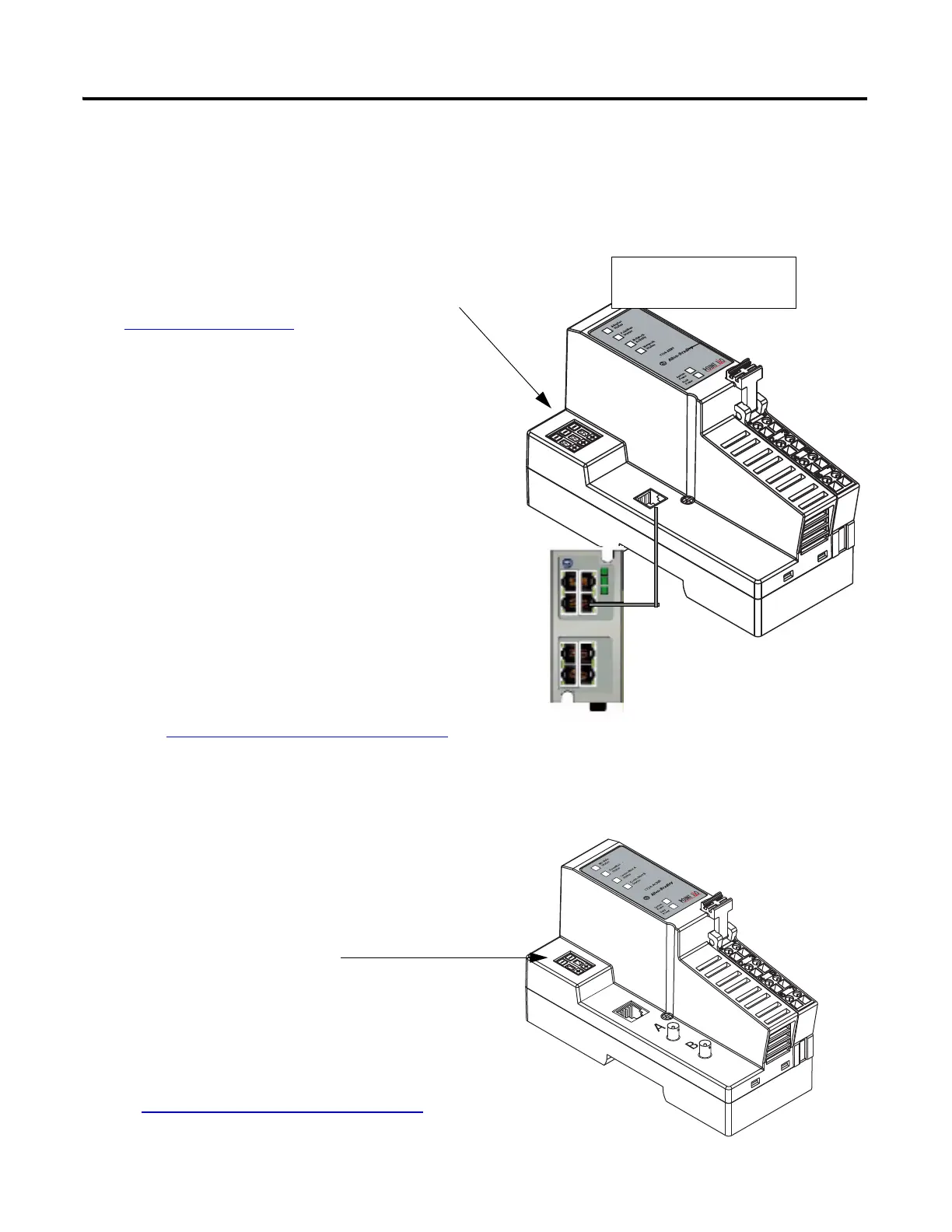
Mount and Connect the Network Adapter
EtherNet/IP 1734-AENT adapter
ControlNet 1734-ACNR adapter
1. Locate the Ethernet address (MAC), found
next to the label. Record the Ethernet address
(MAC) for the POINT I/O adapter on the
Network Worksheet
.
This address is used to set the IP address later
in the quick start.
2. Set the address to a value greater than or
equal to 256.
This example uses 999.
3. Remove the safety end cap.
4. Press the adapter onto the DIN rail.
5. Insert an Ethernet cable.
Go to Mount the POINT I/O Modules
.
00:00:BC:21:44:8A
Ethernet Address
Example Address
1. Remove the safety end cap.
2. Press the adapter onto the DIN rail.
3. Set the node address.
This example uses node 02.
4. Connect a ControlNet tap to the A port.
Go to Mount the POINT I/O Modules
.

Table of Contents

Other manuals for Allen-Bradley PowerFlex 40

Questions and Answers:

Question and Answer IconNeed help?

Do you have a question about the Allen-Bradley PowerFlex 40 and is the answer not in the manual?

Allen-Bradley PowerFlex 40 Specifications

General IconGeneral
Output Voltage0 to Input Voltage
EnclosureIP20
Control MethodV/Hz, Sensorless Vector Control
CommunicationRS485
Frequency0 to 400 Hz
ProtectionOverload, Overvoltage, Undervoltage, Short Circuit
Operating Temperature-10 to 50°C (14 to 122°F)
Storage Temperature-40...70 °C (-40...158 °F)
Humidity5% to 95% non-condensing
Input Voltage200-240V AC, 380-480V AC, 500-600V AC (depending on model)

Related product manuals