EasyManuals Logo

Allen-Bradley PowerFlex 40 User Manual

Allen-Bradley PowerFlex 40
218 pages
To Next Page IconTo Next Page
To Previous Page IconTo Previous Page
Page #128 background imageLoading...
Page #128 background image
128 Publication IASIMP-QS001C-EN-P - October 2009
Chapter 11 Add Distributed I/O Modules to the Project
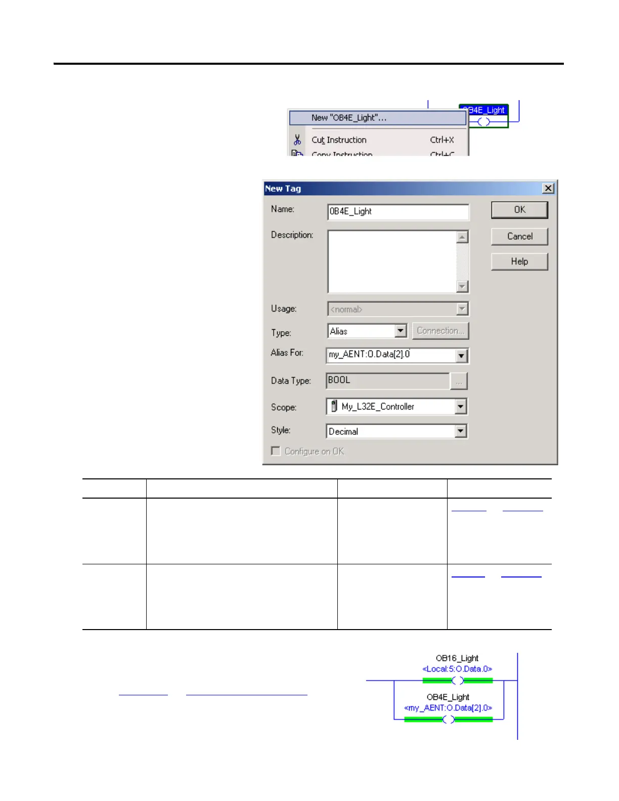
5. From the Type pull-down,
choose Alias.
6. From the Alias For pull-down
menu, browse to find the
addresses recorded below.
7. Click OK.
Go to page 134
to Download the Project.
For Select This Address Example From
EtherNet/IP
_______:O.Data[__].__
my_AENT:O.Data[2].0 Step 14 on page 117
ControlNet
_______:O.Data[__].__
My_ACNR:O.Data[2].0 Step 14 on page 117
adapter
name
output
module
slot #
any
bit
adapter
name
output
module
slot #
any
bit
4. Right-click the Light and select
New ‘xxxx_Light’.
EtherNet/IP
shown

Table of Contents

Other manuals for Allen-Bradley PowerFlex 40

Questions and Answers:

Question and Answer IconNeed help?

Do you have a question about the Allen-Bradley PowerFlex 40 and is the answer not in the manual?

Allen-Bradley PowerFlex 40 Specifications

General IconGeneral
Output Voltage0 to Input Voltage
EnclosureIP20
Control MethodV/Hz, Sensorless Vector Control
CommunicationRS485
Frequency0 to 400 Hz
ProtectionOverload, Overvoltage, Undervoltage, Short Circuit
Operating Temperature-10 to 50°C (14 to 122°F)
Storage Temperature-40...70 °C (-40...158 °F)
Humidity5% to 95% non-condensing
Input Voltage200-240V AC, 380-480V AC, 500-600V AC (depending on model)

Related product manuals