ZA-V BAG0087.11
5.4 Agitator
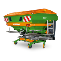
The spiral agitators (Fig. 14/1) in the hopper tips
ensure uniform fertiliser flow to the spreading
discs. The slow-rotating, spiral-
of the agitator carry the fertiliser evenly to the
corresponding outlet opening.
The PTO shaft is responsible for the drive. The
speed reduction is attained by means of a free-
wheel.
14
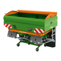
5.5 Dosing slider
Fig. 15
electronically with the control terminal.
In this case, dosing sliders (Fig. 15/2) operated by setting mo-
tors (Fig. 15/1) release a range of different diameters at the out-
let openings (Fig. 15/3).
The electrically shut metering shutter closes the outlet opening
in the tank.
• Manually using the setting lever (Fig. 15
/3) by adjusting different
opening widths of the outlet opening (Fig. 15/2). The required
shutter position in each case is determined either according to
the setting chart or using the sliding ruler.
The metering shutter is actuated hydraulically to open and close
the outlet opening (Fig. 15/4).
As the spreading properties of the fertiliser are subject to considera-
ble fluctuations, it is recommended that a spread rate check be car-
ried out for the selected slider position.

 Loading...