Maintenance and Troubleshooting | 5-33
c. Wearing insulated gloves, grasp the Measuring Cell and carefully
pull it straight out from the Heater Plate and Cell RTD (Figure
5-9). Once the Measuring Cell has cleared the Cell RTD, swing the
Optical Bench Assembly outward, away from the analyzer.
To help maintain the temperature inside the Oven, close the Oven
door while working on the Measuring Cell.
7. While holding the Optical Bench by its upper portion or Measuring
Cell, remove the outermost pivot pin from the blue Support Arm Yoke
and carefully remove it from the analyzer.
While removing the Optical Bench from the Electronics Enclosure, do
not support the assembly by its circuit boards or source lamps.
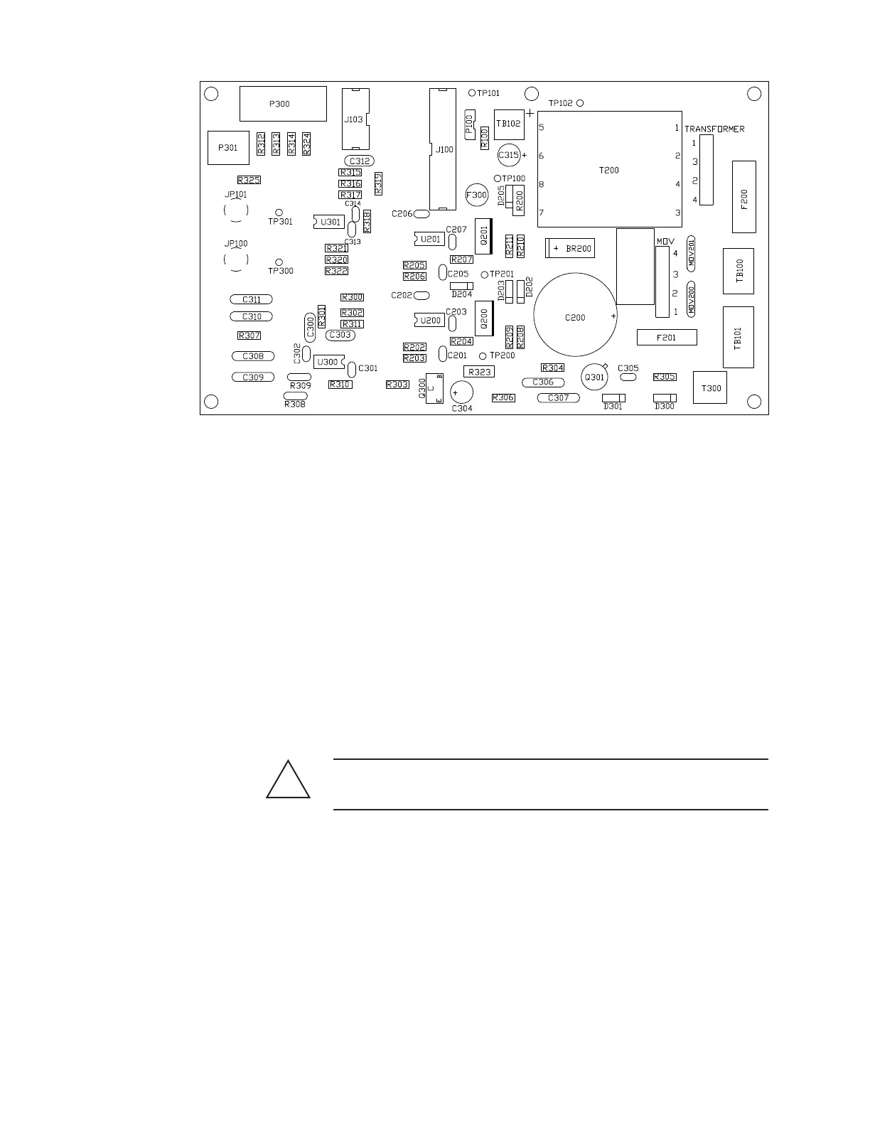
Figure 5-4.
Optical Bench board
layout.
!
CAUTION
 Loading...


