Page 2–28
UPLC-II™ System Manual
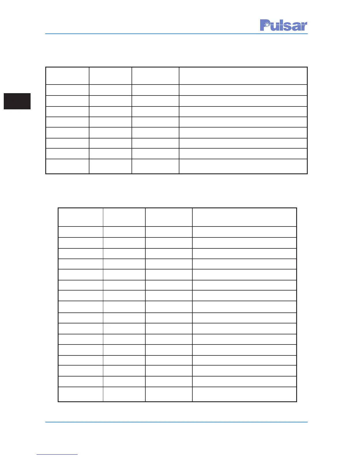
PC Key TX POWER TX OUTPUT CONDITION FOR THIS KEYING
POWER OFF BOOST 52B INPUT STATE
Not Activated Not Activated Not Activated Send HF at Low Power Output
Not Activated Not Activated Activated Send HF at High Power Output
Not Activated Activated Not Activated Transmitter Output Power off
Not Activated Activated Activated Transmitter Output Power off
Activated Not Activated Not Activated Send LF at Low Power Output
Activated Not Activated Activated Send LF at High Power Output
Activated Activated Not Activated Transmitter Output Power Off
Activated Activated Activated Transmitter Output Power Off
Table 2–16. Channel: FSK, Function: 2 Frequency Phase Comparison Relaying
TRIP A TRIP B TX TX OUTPUT CONDITION FOR THIS
KEY KEY POWER OFF KEYING INPUT STATE
Not Activated Not Activated Not Activated Send F3 (Guard) at Low Level Output
Not Activated Not Activated Not Activated Send F3 (Guard) at Low Level Output
Not Activated Not Activated Activated Transmitter Output Power Off
Not Activated Not Activated Activated Transmitter Output Power Off
Not Activated Activated Not Activated Send F2 (Trip B) at High Level Output
Not Activated Activated Not Activated Send F2 (Trip B) at High Level Output
Not Activated Activated Activated Transmitter Output Power Off
Not Activated Activated Activated Transmitter Output Power Off
Activated Not Activated Not Activated Send F4 (Trip A) at High Level Output
Activated Not Activated Not Activated Send F4 (Trip A) at High Level Output
Activated Not Activated Activated Transmitter Output Power Off
Activated Not Activated Activated Transmitter Output Power Off
Activated Activated Not Activated Send F1 (Trip A & B) at High Level Output
Activated Activated Not Activated Send F1 (Trip A & B) at High Level Output
Activated Activated Activated Transmitter Output Power Off
Activated Activated Activated Transmitter Output Power Off
Table 2–17. Channel: FSK, Function: 4 Frequency Directional Comparison Relaying
 Loading...