January 2016 Page 3–19
Chapter 3. Applications
3
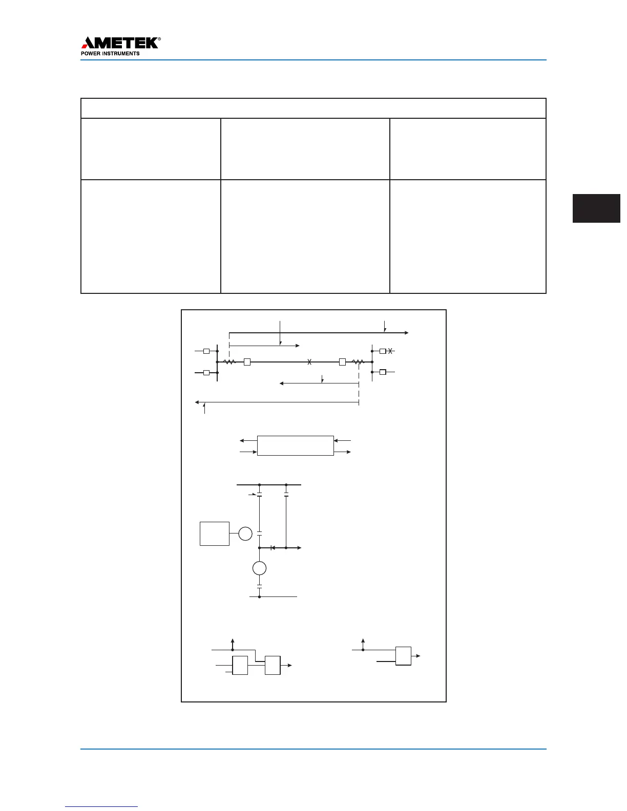
OPERATION FOR EXTERNAL AND INTERNAL FAULTS
Table 3–5. Operation of the Underreaching Transfer Trip Scheme
Type of Fault Events at Station G Events at Station H
External (F
E
) P
1
does not operate.
No channel signal sent to H.
No trip.
P
2
does not operate.
No channel signal sent to G.
No trip.
Internal (F
I
)
(Fault near station H)
P
1
does not operate.
No channel signal sent to H.
†
(FD
1
operates).
Transfer-trip (f
2
) from sta-
tion H operates RR or
inputs to AND (or OR if non-
permissive).
Trip.
P
2
operates and trips direct-
ly.
Transfer-trip signal keyed to
station G.
†
(FD
2
operates).
Trip.
† Omitted in non-permissive systems.
Breaker 1 Trip Fault Detectors (P
1
) Breaker 1 Permissive Fault Detectors (FD
1
)
Breaker 2 Trip Fault Detectors (P
2
)
Breaker 2 Trip Fault Detectors (P
2
)
Protected Line
G
H
F
I
F
E
1 2
Contact Logic (per Terminal)
P
FD
Trip
Solid State Logic (per Terminal)
Channel
except Power Line Carrier
Audio Tone
Receiver f
2
Audio Tone
Receiver f
1
Audio Tone
Transmitter f
1
Audio Tone
Transmitter f
2
RR
Audio
Tone
Receiver
RR
Trip
Coil
52a
FD P
Key Audio Tone Transmitter
to Remote Station
Key Audio Tone Transmitter
to Remote Station
Key Audio Tone Transmitter
to Remote Station
Audio Tone
Receiver
Omit and Bypass
for Non-Permissive
Schemes
AND OR
Permissive Schemes
Non-Permissive Schemes
P
Trip
Audio Tone
Recovery
OR
Figure 3–10. Basic Logic Diagrams for Underreaching Transfer Trip Systems
 Loading...