Page 3–20
UPLC-II™ System Manual
the receiver’s trip positive output. The
other wave, which has positive output
during the negative half-cycle of the
sequence current network, is com-
pared to the receiver’s trip neg. output
in a second comparison circuit.
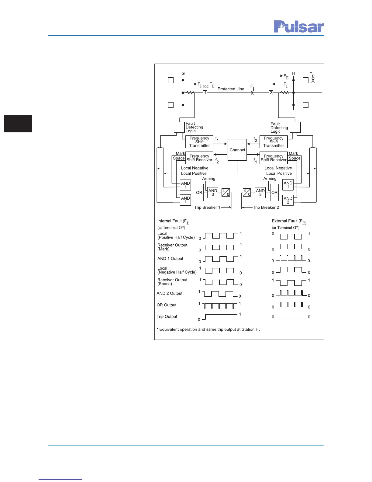
On internal faults, the positive half-
cycle of the local square wave lines up
with the received trip positive output
to provide an AND-1 output. On the
negative half-cycle, this local square
wave lines up with the received trip
negative output to provide an AND-2
output. If an arming signal is received
(FD
2
and/or 21P) and either AND-1 or
AND-2 output exists for 4ms, an input
to the trip flip flop initiates breaker
tripping. The same operation occurs at
both terminals, tripping breakers 1 and
2 simultaneously on either half-cycle
of fault current.
For tripping, both the trip positive and
trip negative frequencies must be
transmitted through the internal fault
via Power-Line Carrier channels. If
these frequencies are not received, the
receiver detects a loss of channel and
clamps both outputs to a continuous
positive state. This loss of channel
clamp enables both comparison cir-
cuits, allowing the system to trip on
the local square wave input only. After
150ms, the system output clamps
these to the zero state. At this point,
the system cannot trip and is locked
out. An alarm indicates loss of chan-
nel.
For external faults, the reversal of cur-
rent at one end shifts the square waves
essentially 180°. As a result, neither AND-1 nor AND-2 has the sustained output required to operate the
4ms timer. No trip occurs at either line terminal.
Figure 3–11. Basic Operation of the Dual
Phase Comparison Pilot Relaying System
 Loading...