Page 3–24
UPLC-II™ System Manual
AND
P
AND
N
OR
Comparison
AND
Arming Input-Current Detector (CD)
Channel Security Checks
Remote
Square Waves
from Channel
Local
Square
Waves
Positive
Negative
Trip
Note:
X = 3 Milliseconds for the Phase Subsystems
4 Milliseconds for Ground
X
0
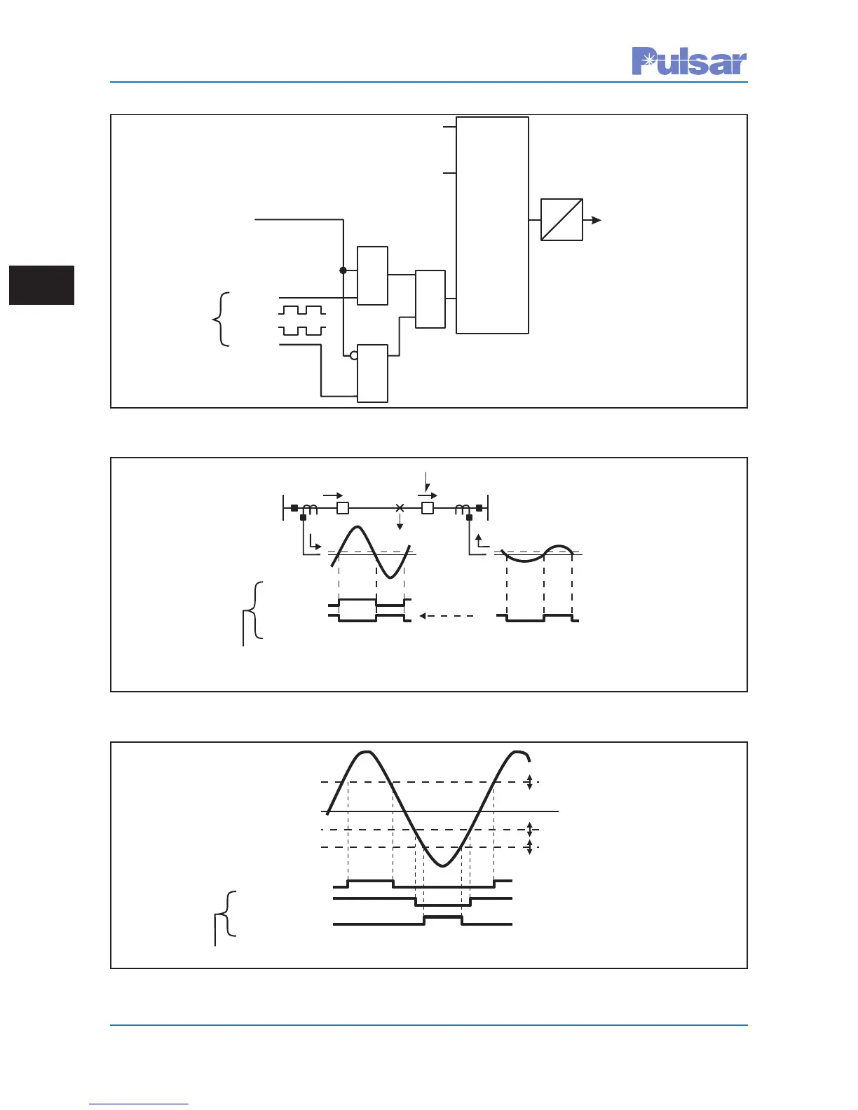
Figure 3–13. Basic Operation of the Segregated Phase Comparison System
I
F
I
G
I
H
Outfeed for an Internal Fault (See Text)
Fault
Local
Square Wave
Remote
Square Wave
External Line Up
Note: Comparison at Both Terminals sees Fault as External.
Keying
Square
Wave
Figure 3–14. Conventional Phase Comparison Response to an Outfeed Condition Block Tripping
Typical Settings
+3A
-2A
-4A
Trip Positive
Trip Positive
Trip Negative
Trip Negative
Local Positive
Local Positive
Local Negative
Local Negative
1
0
1
0
Keying Square Wave
Zero Axis
I
Key
(1)
(0)
(0)
(1)
Figure 3–15. Typical Threshold Setting for Offset Keying

 Loading...