AD9361 Reference Manual UG-570
| Page 121 of 128
Power Up 1.3 V Analog Supply on the AD9361 with an
LDO
The evaluation boards power the 1.3 V analog supply of the
AD9361 with a LDO. The selection of the LDO is important not
only from a power management perspective but also from a
performance perspective. A LDO with poor PSRR will degrade
the RF performance of the part. An LDO with poor noise
characteristics will introduce noise in the receiver spectrum as
well as the transmitter spectrum.
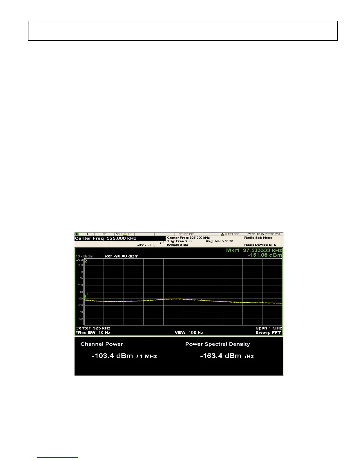
Figure 88 shows the close in noise spectrum of the ADP1755
that we have used to power the 1.3 V analog supply. This
spectrum shows a clean and a low noise floor that is beneficial
to achieving the best performance from the AD9361. Any spurs
or noise from the power supply within a 1 MHz span will
appear on the local oscillator frequency and manifest itself as
transmitter phase noise. Similarly, it will also affect the receiver
down conversion performance. Figure 90 shows the summary
of the effects of power supply noise on the phase noise
performance of the part. The phase noise plot shows that the
AD9361 performance degrades when it is powered with
ADP1706 as compared to the performance with an ADP1755.
Power Up 1.3 V Analog Supply on the AD9361 with
Switching Regulator
Using a switching regulator to power the AD9361 provides
great efficiency that is easily transferrable to an overall cost
reduction. A switching regulator can power the 1.3 V analog
power supply of the AD9361. However, choosing the right
switching regulator is crucial to getting the best performance
from the AD9361. During the selection process, the following
characteristics of the switching regulator are important: noise
floor, output noise spectrum, switching frequency, slew rate,
maximum output capacitance.
Noise Floor
It is beneficial to have a switching regulator with a low noise
floor. The noise floor characteristics of the switching regulator
change with the load. The noise floor is typically worse when
the regulator is not loaded but turned on. 1/f noise affects the
low frequency performance of the regulator. At higher
frequencies, the switching action of the regulator introduces
noise at the switching frequencies and its harmonics; in
addition, rapid transitions of the switching frequency may
excite the parasitic capacitance of the regulation circuit and
create high frequency oscillations, in this respect layout and
passive component selection are also important to minimize the
noise generated by the switching regulator.
Fig
ure 88. Noise Floor of ADP1755 Powering the 1.3 V Analog Plane

 Loading...


