Instrument Overview 2-3 Connector Panels
MS2090A UG PN: 10580-00444 Rev. U 2-5
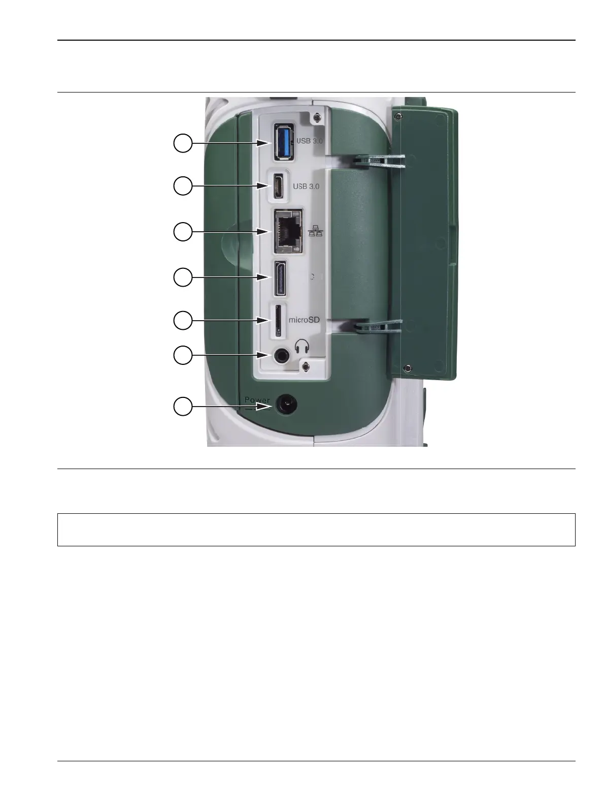
Side Connector Panel
Figure 2-3 shows the MS2090A side connector panel.
1. USB Interface – Type A: The Field Master Pro has three Type A USB connectors that accept USB storage
devices for saving measurements, setup data, and screen images. Two connectors are located on the top panel
and one more is located on the side panel. To ensure the device or its data does not become corrupted, touch the
eject icon to eject (unmount) the USB memory device before it is unplugged from the USB port (see
Section “Title bar” on page 2-13).
2. USB Interface – Type C: The USB Type-C port is used to connect the Field Master Pro directly to a PC and
provides a remote SCPI programming interface via USBTMC (USB Test and Measurement Class). Refer to the
MS2090A programming manual for remote SCPI control setup and command.
3. LAN Connection: The RJ-45 connector is used to connect the Field Master Pro to a local area network or
directly to a PC with an Ethernet crossover cable. See “Ethernet Connection” on page 2-30 for more details.
4. Data Out Port: The Data Out port is used for IQ Streaming. Refer to IQ Capture/Streaming measurement
guide (10580-00490) for more information. This is a multi-purpose, hot pluggable input/output (I/O) interface.
Figure 2-3. Side Connector Panel
Note
The MS2090A is compatible with external USB memory devices that have an integrated keypad and
are FIPS compliant using AES 256-bit encryption.
u
Data