2-10 Settings Menu Instrument Overview
2-30 PN: 10580-00444 Rev. U MS2090A UG
• The remote program may connect to the instrument IP address or to its HOSTNAME (Ethernet only). If
using DHCP instead of a static IP, using the HOSTNAME may be more reliable for finding an instrument
on a network.
• The instrument supports multicast DNS (mDNS). This allows a client that also supports mDNS to
connect to the instrument using its hostname without needing to setup a local name server. To use
mDNS add the .local top-level domain to the instrument hostname. For example, if the instrument’s
hostname is "AnritsuInstrument", an mDNS client could access the instrument with
"AnritsuInstrument.local".
• You may need to contact your network administrator to ensure network security policies, anti-virus, and
firewall settings do not block access to the controlling computer and its ports.
The MS2090A can be configured for Dynamic Host Configuration Protocol (DHCP), an Internet protocol that
automates the process of setting IP addresses for devices that use TCP/IP, and is the most common method of
configuring a device for network use.
To determine if a network is set up for DHCP, connect the instrument to the network and select DHCP
protocol. Power cycle the instrument. If the network is set up for DHCP, the assigned IP address should be
displayed in the network settings.
Ethernet Connection
Interface between the instrument and other devices on the network is via a category five (CAT-5) interface
cable connected to a network. This cable uses four twisted pairs of insulated copper wires terminated into an
RJ45 connector. CAT-5 cabling is capable of supporting frequencies up to 100 MHz and data transfer speeds up
to 1 Gbps, which accommodates 1000Base-T, 100Base-T, and 10Base-T networks. CAT-5 cables are based on
the EIA/TIA 568 Commercial Building Telecommunications Wiring Standard developed by the Electronics
Industries Association. A pinout diagram is shown in Table 2-1.
Integrated into the RJ45 connector are two LEDs that illuminate as follows:
• LED 1 Off: 10 Mbit/s LAN connection
• LED 1 Orange: 100 Mbit/s LAN connection
• LED 1 Green: 1000 Mbit/s LAN connection
• LED 2 Amber/Yellow: On or blinking indicates LAN traffic
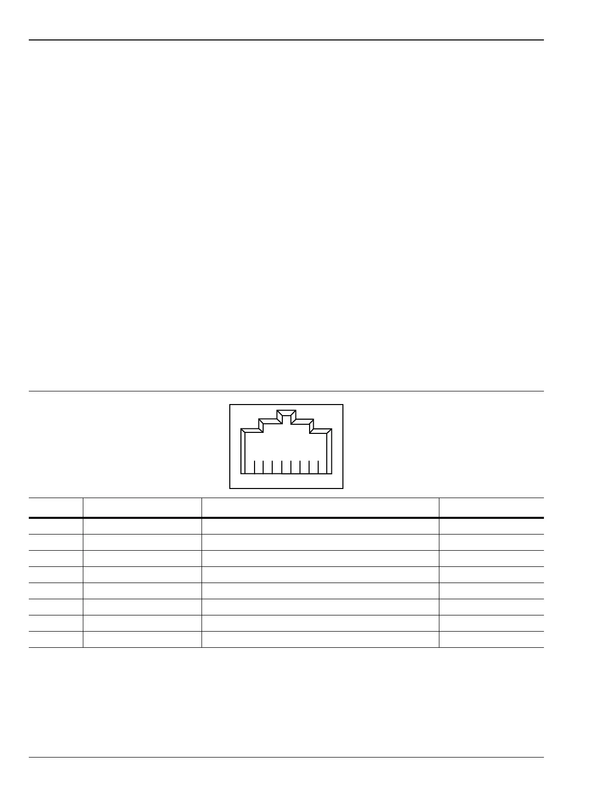
Table 2-1. 8-pin Ethernet RJ45 Connector Pinout Diagram
Pin Name Description Wire Color
1 TX+ Transmit data (> +3 volts) White/Orange
2 TX– Transmit data (< –3 volts) Orange
3 RX+ Receive data (> +3 volts) White/Green
4 – Not used (common termination) Blue
5 – Not used (common termination) White/Blue
6 RX– Receive data (< –3 volts) Green
7 – Not used (common termination) White/Brown
8 – Not used (common termination) Brown