Section 5 Remote Control
5-8
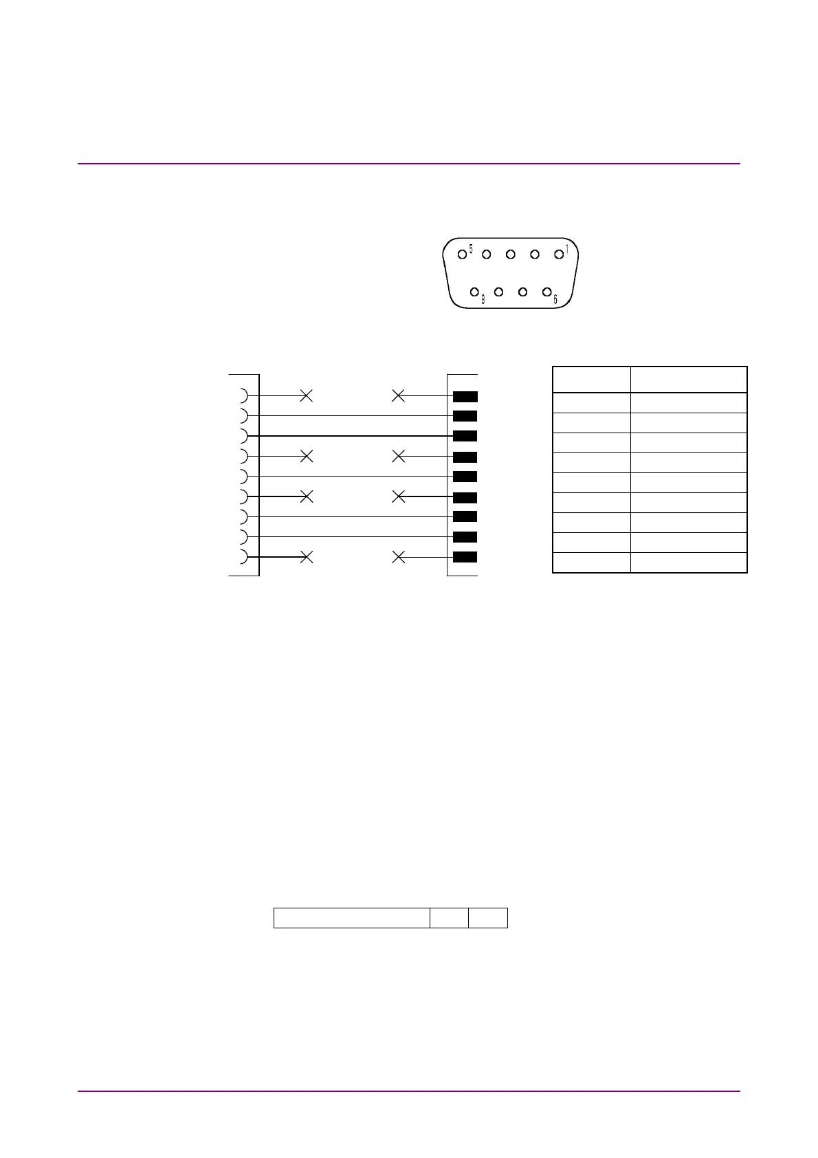
Pin assignment of the RS-232C connector is shown in the figure below:
Fig. 5.3.2-1 Pin assignment of RS-232C connector
No Name
1 (NC)
2 RD
3 TD
4 (NC)
5 GND
6 (NC)
7 RTS
8 CTS
9 (NC)
NC: Not connected
Fig. 5.3.2-1 Interfacing to personal computer
Note
:
The use of the Anritsu application parts "J1256A" is recommended.
5.3.3 Initializing device
The MP8931A supports the *RST command (refer to GPIB section 5.2.5)
for device initialization when using RS-232C interface. Device status
after power-on is the same as that for GPIB interface.
5.3.4 Transmission format
Transmission format is shown below:
Message CR LF
Message (ASCII code): Command/query/response. Up to 256 bytes.
CR (0DH): Receives LF to indicate the end of transmission.
LF (0AH): Indicates the end of transmission with CR.
Xoff (13H): Indicates suspend of transmission.
Xon (11H): Indicates resumption of transmission.
D-sub 9P female
MP8931A
CD
RD
TD
DTR
GND
DSP
RTS
CTS
RI
(NC)
TD
RD
(NC)
GND
(NC)
CTS
RTS
(NC)
PC
D-sub 9P male
RS-232C straight cable