2-2 Spectrum Analyzer Function Verification Performance Verification 1
2-14 PN: 10580-00177 Rev. D MS2721B MM
11. Disconnect the power sensor from the "output" of the splitter and connect the splitter "output" to the
MS2721B Spectrum Analyzer RF In connector through the Anritsu Model 34NN50A adapter.
12. Turn on the RF of the MG3692x and the 8648D signal generator.
13. Press the Shift key and then the Trace (5) key. Press Trace A Operations, and set # of Averages to 2.
14. After two sweeps have occurred ("Trace Count 2/2" appears on the left of the display), turn on a marker
and press Peak Search. Record the amplitude of the signal at 600.151 MHz in Table A-5, “600 MHz TOI
Test” on page A-3.
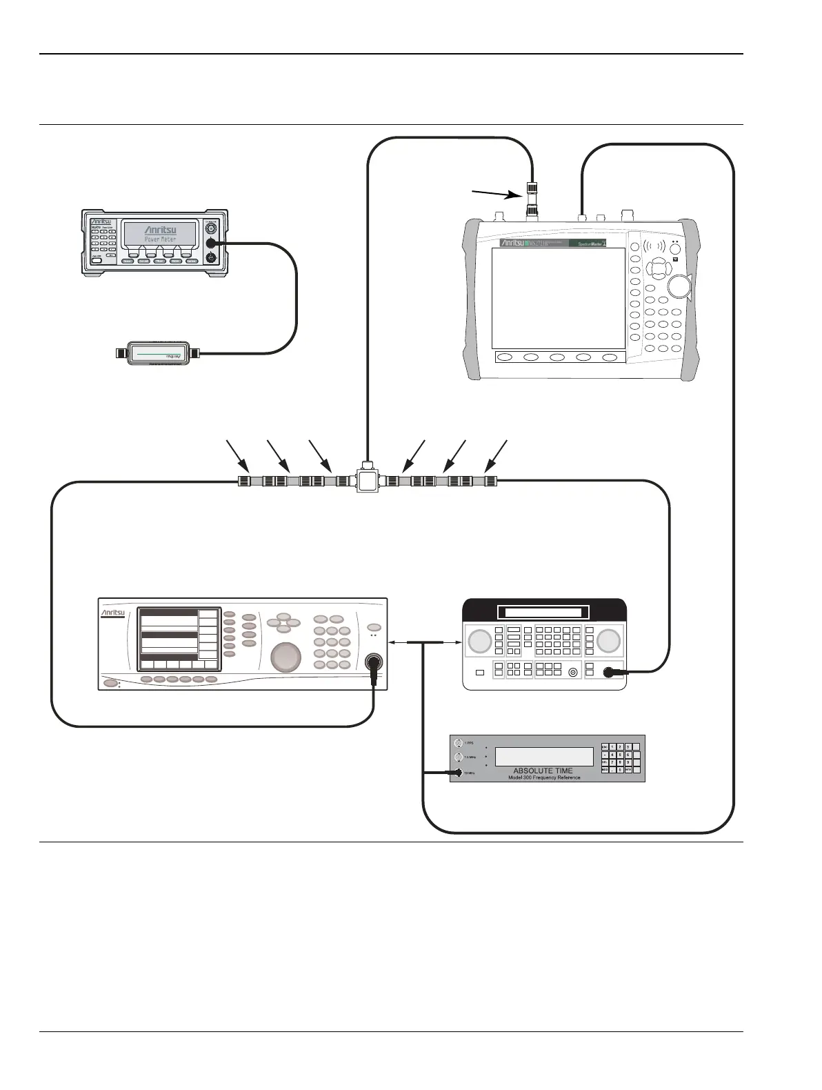
Figure 2-6. 600 MHz TOI Verification Test Setup
7
1
2
3
4
5
6
8
9
0
.
+/-
ML2438A Power Meter
Sensor
10 MHz Reference
Power
Splitter
1870A
Attenuators
MG3692A
Agilent 8648D
Attenuators
Adapter
34NN50A
6 dB 20 dB2 dB 20 dB 6 dB 2 dB
To
Rear
MS2721B

 Loading...


