ASE2000 V2 Communication Test Set User Manual 127
5. On one of the test copies, select “File > Simulate RTU” or select the “Simulate RTU” icon.
6. On the other test set copy, move the mouse pointer over the “Data” exchange name in the
“Exchange List” view then select “File > Send Continuously” or select the “Send Continuously”
icon.
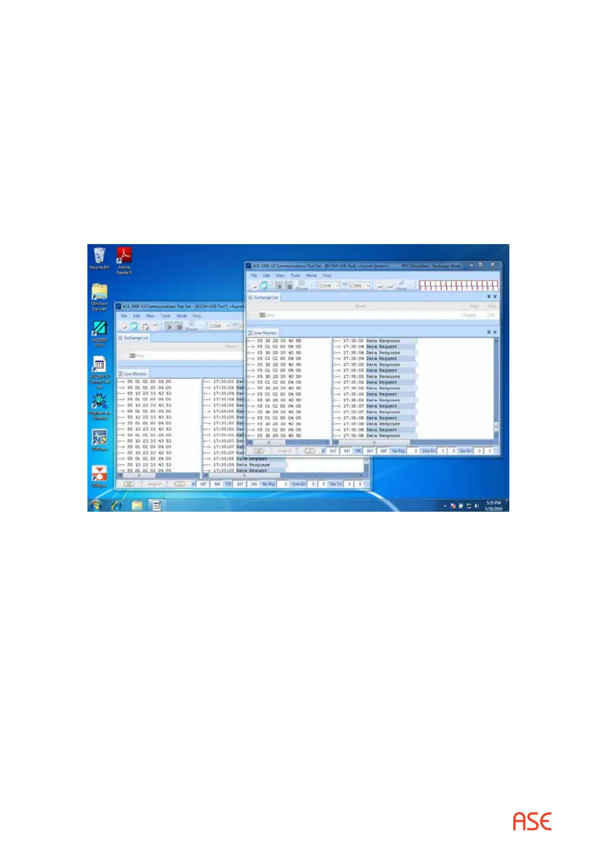
7. At this point, if the BCOM-USB device is working properly, the screen should look similar
to the example below. In the Line Monitor view for each test set window there should be a
series of “Data request” and “Data Response” entries in the interpreted data section and the
following data in the raw data section:
--> 55 01 02 03 04 05
<-- 55 10 20 30 40 50
8. If the test set screen looks similar to the above screen, the BCOM-USB device is most likely
installed and functioning correctly.
 Loading...