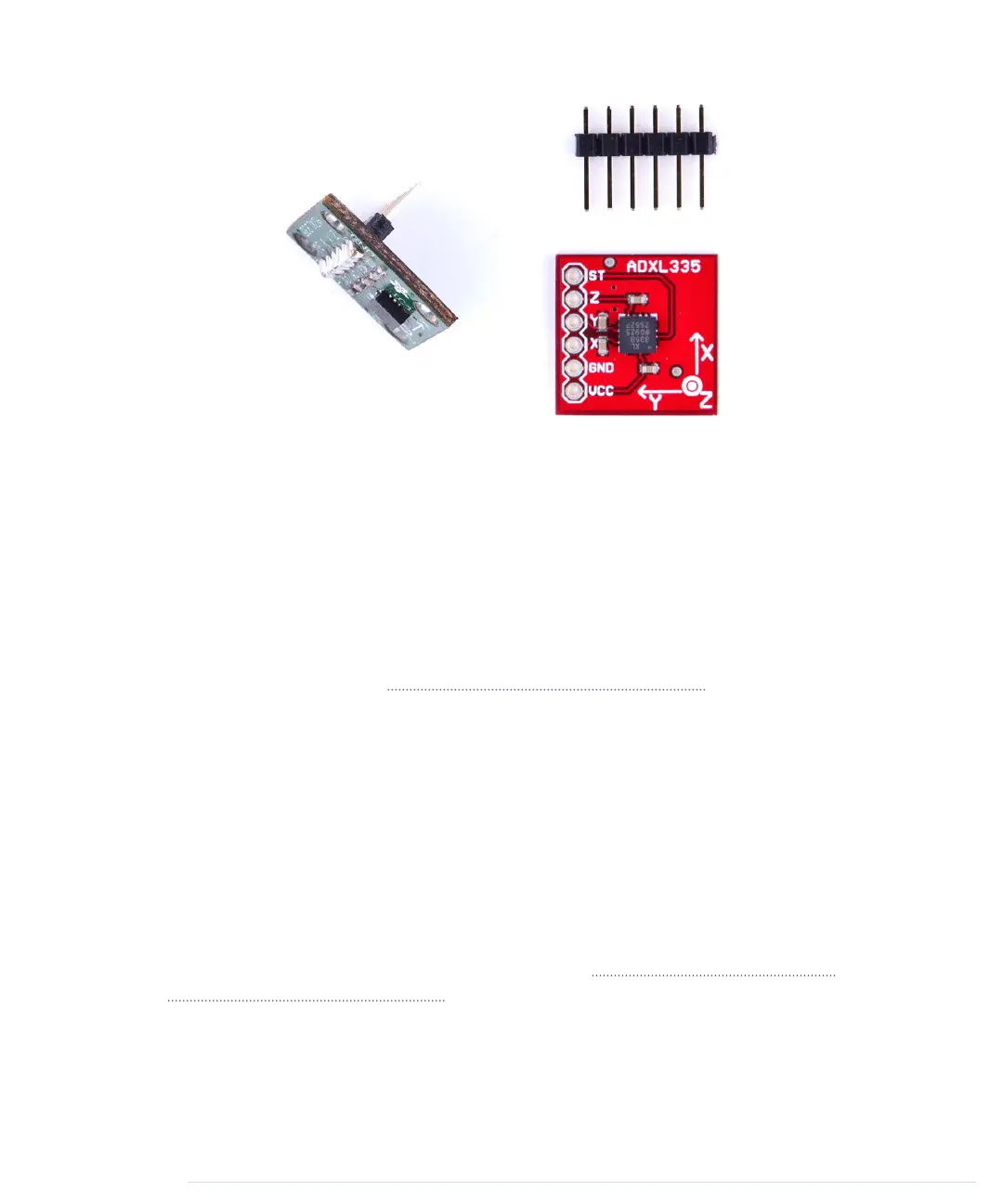
This picture shows a breakout board containing an ADXL335 sensor on the
right. The sensor is the small black integrated circuit (IC), and the rest is just
a carrier to allow connections. On the top, you see a 6-pin 0.1-inch standard
header. The sensor has six connectors, labeled GND, Z, Y, X, VCC, and ST.
To use the sensor on a breadboard, solder the standard header to the connec-
tors. This not only makes it easier to attach the sensor to a breadboard, but
it also stabilizes the sensor so it doesn’t move accidentally. You can see the
result on the left side of the photo. (Note that the breakout board on the left
isn’t the same as on the right, but it’s very similar.) Don’t worry if you’ve
never soldered before. In Learning How to Solder, on page 243, you can learn
how to do it.
You can ignore the connector labeled ST, and the meaning of the remaining
connectors should be obvious. To power the sensor, connect GND to the
Arduino’s ground pin and VCC to the Arduino’s 3.3V power supply. X, Y, and
Z will then deliver acceleration data for the x-, y-, and z-axes.
Note that not all breakout boards have the same connectors. Usually, they
have six or seven connectors. Some breakout boards can cope with 5V, while
others only work with 3.3V. Some boards have an input pin named VIN that
you have to connect to one of the Arduino’s power supply pins (5V or 3.3V).
Like the TMP36 temperature sensor we used in Increasing Precision Using a
Temperature Sensor, on page 86, the ADXL335 is an analog device: it delivers
results as voltages that have to be converted into acceleration values. So, the
X, Y, and Z connectors have to be connected to three analog pins on the
Arduino. We connect Z to analog pin 0, Y to analog pin 1, and X to analog
pin 2. (See the following image and double-check the pin labels on the
report erratum • discuss
Wiring Up the Accelerometer • 101
www.it-ebooks.info

 Loading...