Building a Digital-to-Analog Converter (DAC)
The Arduino doesn’t natively support analog output signals, so we need to
find a way around this limitation. The solution is a digital-to-analog converter
(DAC).
1
As the name suggests, such a circuit turns a digital input into an
analog output. You can find DACs in a lot of consumer devices—for example,
in your MP3 player. It turns your digitally encoded music into an analog
sound wave.
One of the most important characteristics of a DAC is its resolution. In our
case we need to generate four different voltage levels to create a video signal.
To encode four voltage levels, we need two bits—that is, our DAC has a 2-bit
resolution. The following table shows how we could map the four binary input
values to their voltage levels.
11100100
Binary input:
1.0V0.6V0.3V0.0VOutput voltage:
We can use two of the Arduino’s digital pins to control the DAC’s input value,
but we still have to find a way to generate different voltages depending on the
pins’ values.
There are several ways to achieve this, but one of the easiest is by using a
binary-weighted DAC. It has the following characteristics:
• You need a resistor for every input bit.
• All resistors have to be in parallel.
• Resistor value for bit #0 is R. For bit #1 it’s 2R, for bit #3 it’s 4R, and so
on.
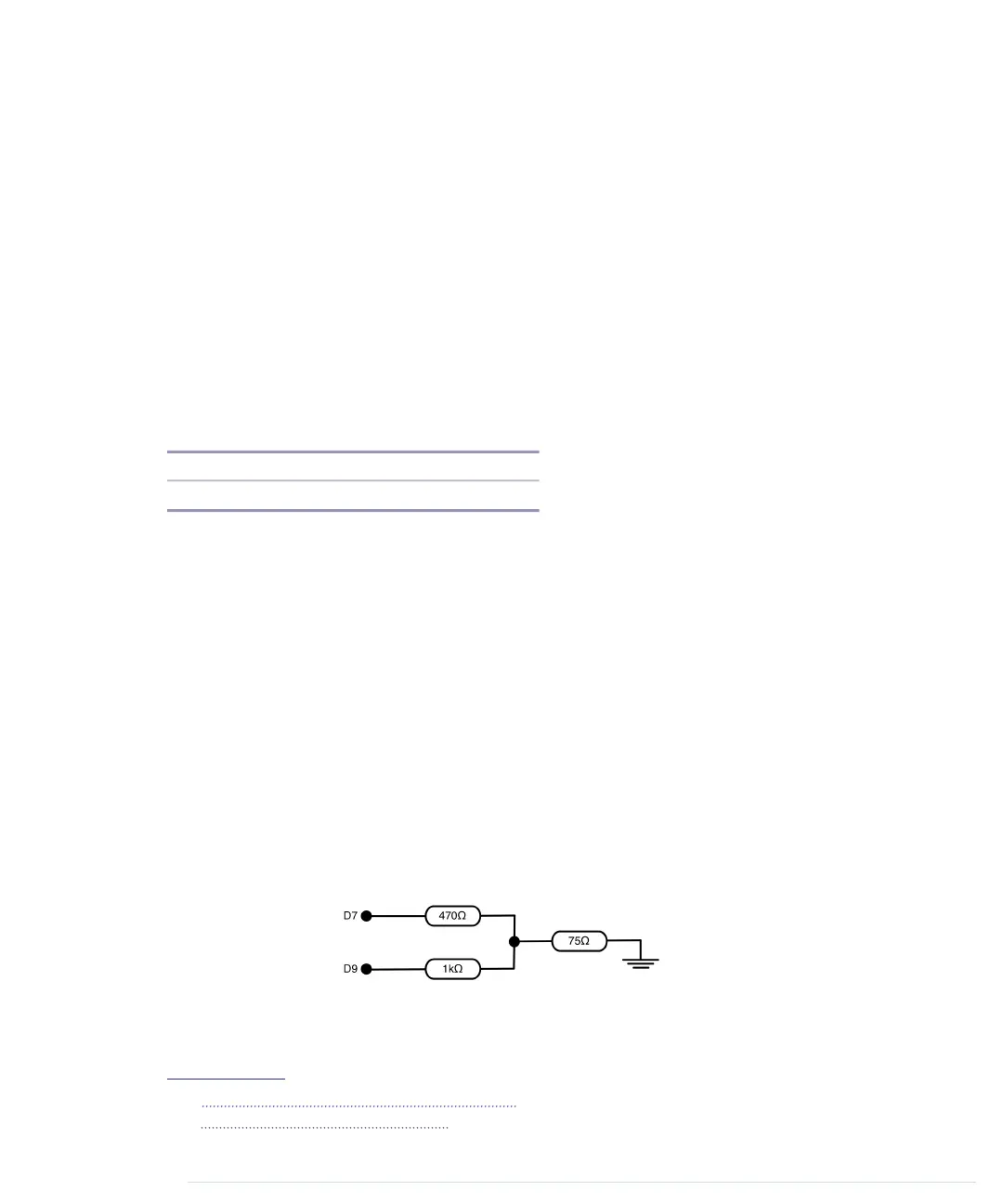
Let’s say we use the Arduino’s digital pins D7 and D9 to control the DAC’s
input value. In the following figure, you can see our DAC’s circuit. You have
to add the 470Ω and 1kΩ resistors yourself, but you get the 75Ω resistor for
free, because it’s part of your TV set’s input connector.
In principle, the binary-weighted DAC is a voltage divider
2
—that is, it turns
an input voltage into a smaller voltage. The output voltage depends on the
1.
http://en.wikipedia.org/wiki/Digital-to-analog_converter
2.
http://en.wikipedia.org/wiki/Voltage_divider
Chapter 8. Generating Video Signals with an Arduino • 130
report erratum • discuss
www.it-ebooks.info

 Loading...