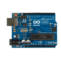
Our test program is as simple as it can be. We define constants for the three
analog pins and initialize the serial port in the
setup
function. Note that we
didn’t set the analog pins to
INPUT
explicitly, because that’s the default anyway.
In the
loop
function, we constantly output the values we read from the analog
pins to the serial port. Open the serial monitor and move the sensor around
—tilt it around the different axes. You should see output like this:
344 331 390
364 276 352
388 286 287
398 314 286
376 332 289
370 336 301
These values represent the data we get for the x-, y-, and z-axes. When you
move the sensor only around the x-axis, for example, you can see that the
first value changes accordingly. In the next section, we’ll take a closer look
at these values.
Finding and Polishing Edge Values
The physical world often is far from perfect. That’s especially true for the data
many sensors emit, and accelerometers are no exception. They vary slightly
in the minimum and maximum values they generate, and they often jitter.
They might change their output values even though you haven’t moved them,
or they might not change their output values correctly. In this section, we’ll
determine the sensor’s minimum and maximum values, and we’ll flatten the
jitter.
Finding the edge values of the sensor is easy, but it cannot be easily automat-
ed. You have to constantly read the sensor’s output while moving it. Here’s
a program that does the job:
MotionSensor/SensorValues/SensorValues.ino
const unsigned int X_AXIS_PIN = A2;
const unsigned int Y_AXIS_PIN = A1;
const unsigned int Z_AXIS_PIN = A0;
const unsigned int BAUD_RATE = 9600;
int min_x, min_y, min_z;
int max_x, max_y, max_z;
void setup() {
Serial.begin(BAUD_RATE);
min_x = min_y = min_z = 1000;
max_x = max_y = max_z = -1000;
}
report erratum • discuss
Finding and Polishing Edge Values • 103
www.it-ebooks.info

 Loading...