resistor values—75Ω, 470Ω, and 1kΩ, in our case. If you set both input sig-
nals to 0V, the output voltage will be 0V, too. That’s how we can create the
SYNC signal.
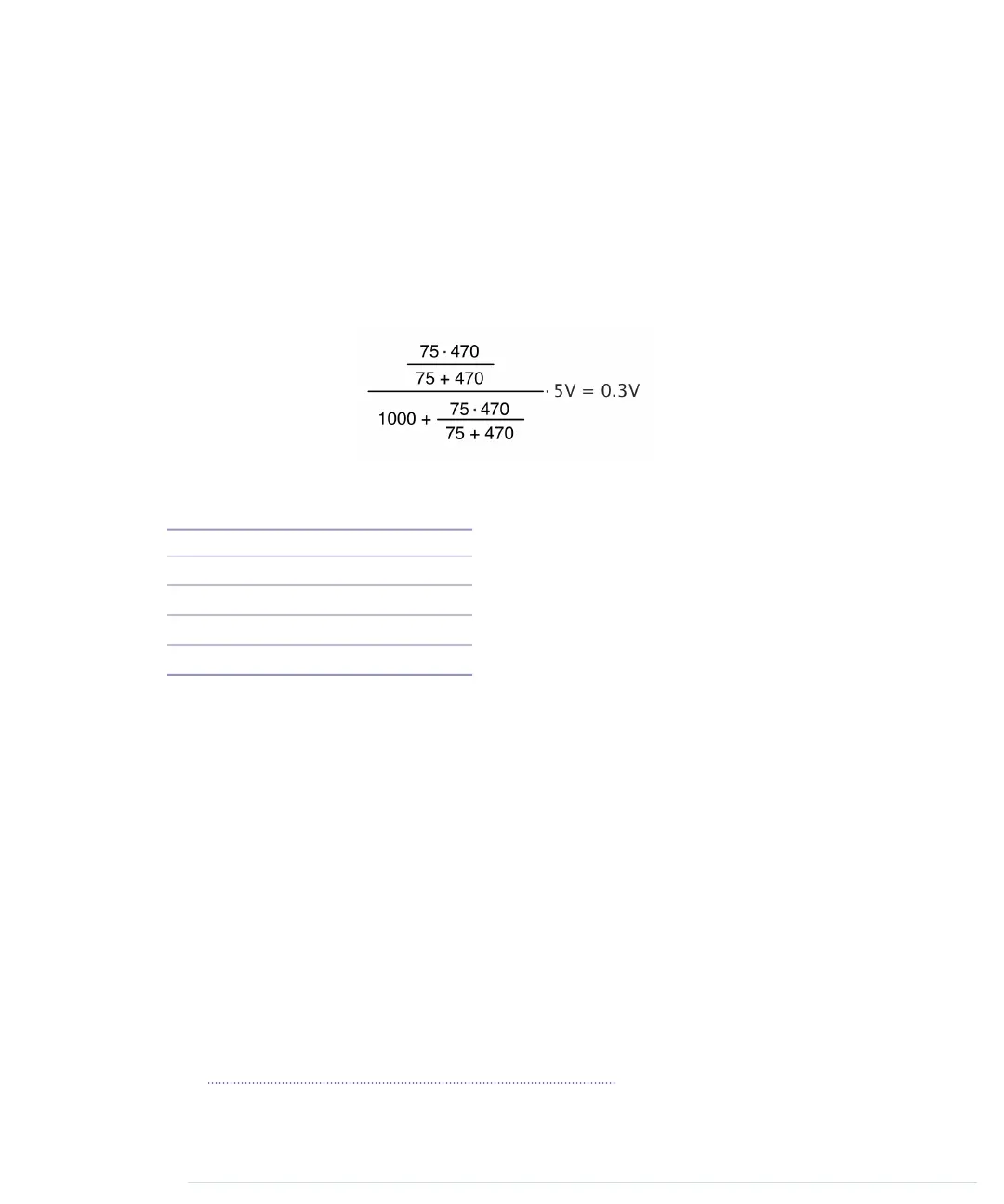
Calculating the output voltage for the remaining three combinations of input
values isn’t rocket science, but the theory and formulas of voltage division
are beyond the scope of this book. Just to give you a feeling, the following
figure shows how to calculate the output voltage when you set D7 to 0V and
D9 to 5V.
The following table shows the corresponding output voltages for all possible
combinations of pin values.
ColorOutput VoltagePin D9Pin D7
SYNC0.0V0V0V
Black0.3V5V0V
Gray0.65V0V5V
White0.95V5V5V
Now you should see why we’ve used a 470Ω and a 1kΩ resistor. The value
1000 is roughly 470 times 2, so the resistor values follow the rules of a
binary-weighted DAC. Also, these two resistors (combined with the TV set’s
75Ω resistor) produce the output voltages we need. Note that the output
voltages don’t exactly match the specification, but in practice the small differ-
ences are negligible.
Connecting the Arduino to Your TV Set
Even with a digital-to-analog converter in place, we still have a problem: the
Arduino doesn’t have an RCA jack—that is, you cannot plug an RCA cable
into an Arduino. We could attach an RCA jack to a breadboard and connect
it to the Arduino, but there’s an easier solution. We’ll modify an RCA cable
and connect it directly to the Arduino.
First, you have to cut off one of the cable’s connectors using a wire cutter.
(See Learning How to Use a Wire Cutter, on page 243, to learn more about wire
cutters.) Then remove about three centimeters of the cable’s outer insulation.
report erratum • discuss
Connecting the Arduino to Your TV Set • 131
www.it-ebooks.info

 Loading...