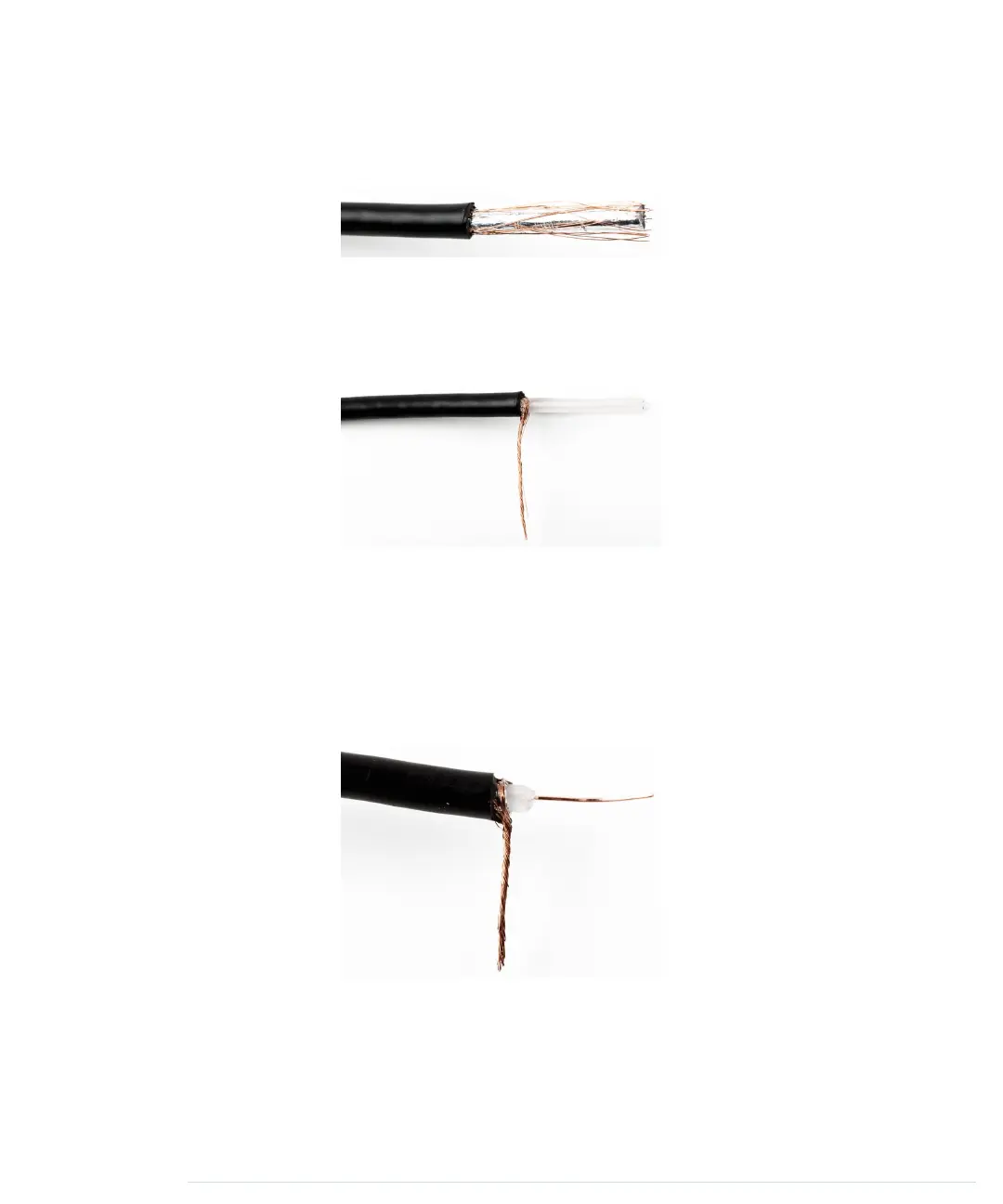
Be careful, because the insulation isn’t very thick. Use the wire cutter to cut
it slightly and then remove it by pushing it slowly toward the cable’s end. The
cable should look like the following image.
As you can see, there’s a mesh of wires below the outer insulation. Bring back
the mesh into wire shape by rubbing it between your thumb and forefinger,
so you can solder it to a solid-core wire later. The result should look like the
following image.
The cable usually also contains an inner insulation made of plastic. Use the
wire cutter again to remove the inner insulation. In my experience, it’s best
to put the insulation between the wire cutter’s blades and then turn the cable
slowly and carefully, increasing the pressure while turning the cable. Be very
careful that you don’t accidentally cut the signal wire! After you’ve cut through
the whole insulation, you can easily remove it. You should now see the cable’s
signal wire, and your cable should look like the following image.
Finally, we have to connect the two resistors to the RCA cable’s signal wire,
and it’s not sufficient to simply knot them together. You have to solder them.
While you’re at it, connect the RCA cable’s ground wire to a piece of solid-core
wire, so you can easily attach it to the Arduino. The following image shows
what it should look like.
Chapter 8. Generating Video Signals with an Arduino • 132
report erratum • discuss
www.it-ebooks.info

 Loading...