BinaryDice/Blink/Blink.ino
const unsigned int LED_PIN = 12;
const unsigned int PAUSE = 500;
void setup() {
pinMode(LED_PIN, OUTPUT);
}
void loop() {
digitalWrite(LED_PIN, HIGH);
delay(PAUSE);
digitalWrite(LED_PIN, LOW);
delay(PAUSE);
}
We’ve built a strong foundation for our project, and in the next section we’ll
build upon it.
First Version of a Binary Die
You’re certainly familiar with a regular die displaying results in a range from
one to six. To emulate such a die exactly with an electronic device, you’d need
seven LEDs and some fairly complicated business logic. We’ll take a shortcut
and display the result of a die roll in binary.
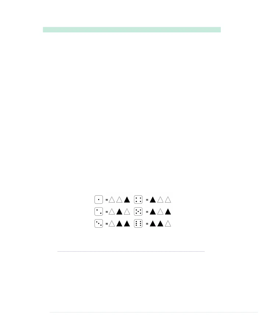
For a binary die, we need only three LEDs to represent the current result. We
turn the result into a binary number, and for every bit that is set, we light
up a corresponding LED. The following diagram shows how the die results
are mapped to LEDs. (A black triangle stands for a shining LED.)
We already know how to control a single LED on a breadboard. Controlling
three LEDs is similar and requires only more wires, LEDs, 1kΩ resistors, and
pins. Figure 11, A first working version of our binary die, on page 46 shows
the first working version of a binary die.
The most important difference is the common ground. When you need ground
for a single LED, you can connect it to the LED directly. But we need ground
for three LEDs now, so we’ll use the breadboard’s rows for the first time.
Connect the row marked with a hyphen (-) to the Arduino’s ground pin, and
report erratum • discuss
First Version of a Binary Die • 45
www.it-ebooks.info

 Loading...