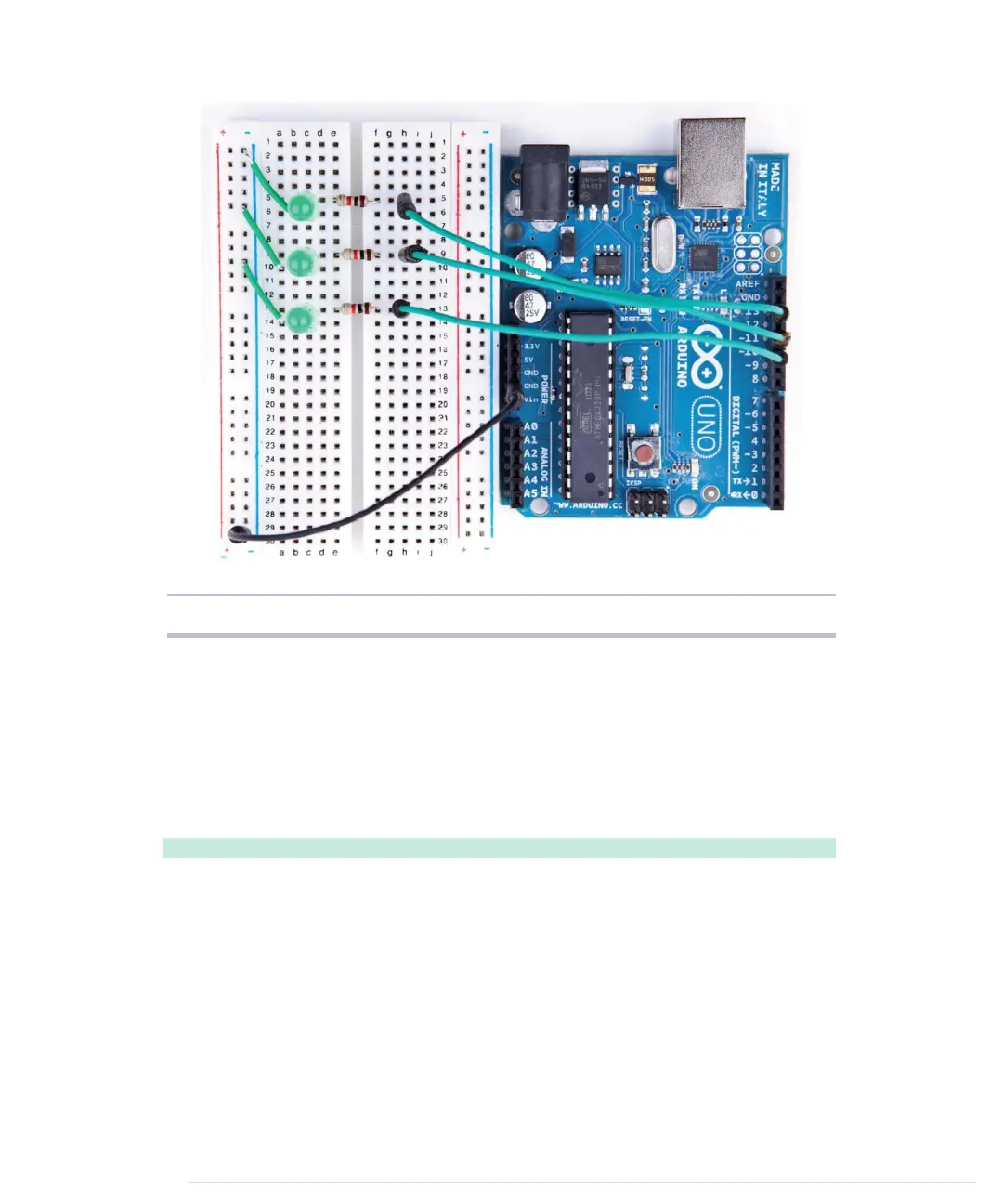
Figure 11—A first working version of our binary die
all sockets in this row will work as ground pins, too. Then you can connect
this row’s sockets to the LEDs using short wires.
Everything else in this circuit should look familiar, because we only had to
clone the basic LED circuit from the previous section three times. Note that
we have connected the three LEDs to pins 10, 11, and 12. The only thing
missing is some software:
BinaryDice/BinaryDice/BinaryDice.ino
const unsigned int LED_BIT0 = 12;
Line 1
const unsigned int LED_BIT1 = 11;
-
const unsigned int LED_BIT2 = 10;
-
-
void setup() {
5
pinMode(LED_BIT0, OUTPUT);
-
pinMode(LED_BIT1, OUTPUT);
-
pinMode(LED_BIT2, OUTPUT);
-
-
randomSeed(analogRead(A0));
10
long result = random(1, 7);
-
output_result(result);
-
}
-
Chapter 3. Building Binary Dice • 46
report erratum • discuss
www.it-ebooks.info

 Loading...