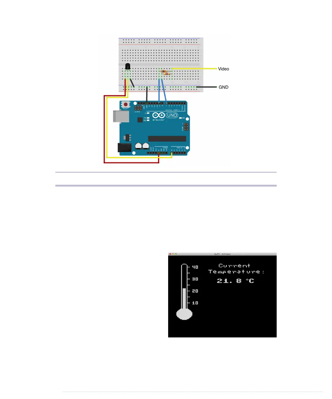
Figure 24—Circuit of the TV thermometer
Don’t get confused by what the circuit for the video signal looks like in the
circuit diagram. That’s how you would build the circuit on a breadboard. Of
course, you can still connect the modified RCA cable directly to the Arduino.
Then connect the circuit for the TMP36 sensor.
Before we dive into the project’s code, have a look at what we’re trying to
build.
On the left side of the screen, you see
a graphical representation of a typical
thermometer. It has a scale ranging
from 5.5 to 40 degrees Celsius. The
thermometer isn’t a static image. The
bar in the middle will grow or shrink
depending on the current tempera-
ture.
On the right side of the screen, we
display the current temperature as
text. All in all, we have to output some
text, and we have to draw some graphics. It’s a perfect opportunity to meet
TVout’s most important functions, so let’s see how it works.
report erratum • discuss
Building a TV Thermometer • 135
www.it-ebooks.info

 Loading...