EasyManua.ls Logo

Arduino uno User Manual

Arduino uno
311 pages
To Next Page IconTo Next Page
To Previous Page IconTo Previous Page
Page #267 background imageLoading...
Page #267 background image
a 0 bit is represented by 0 volts, while 5 volts stands for a 1 bit. (Some proto-
cols use -12V and 12V, respectively.)
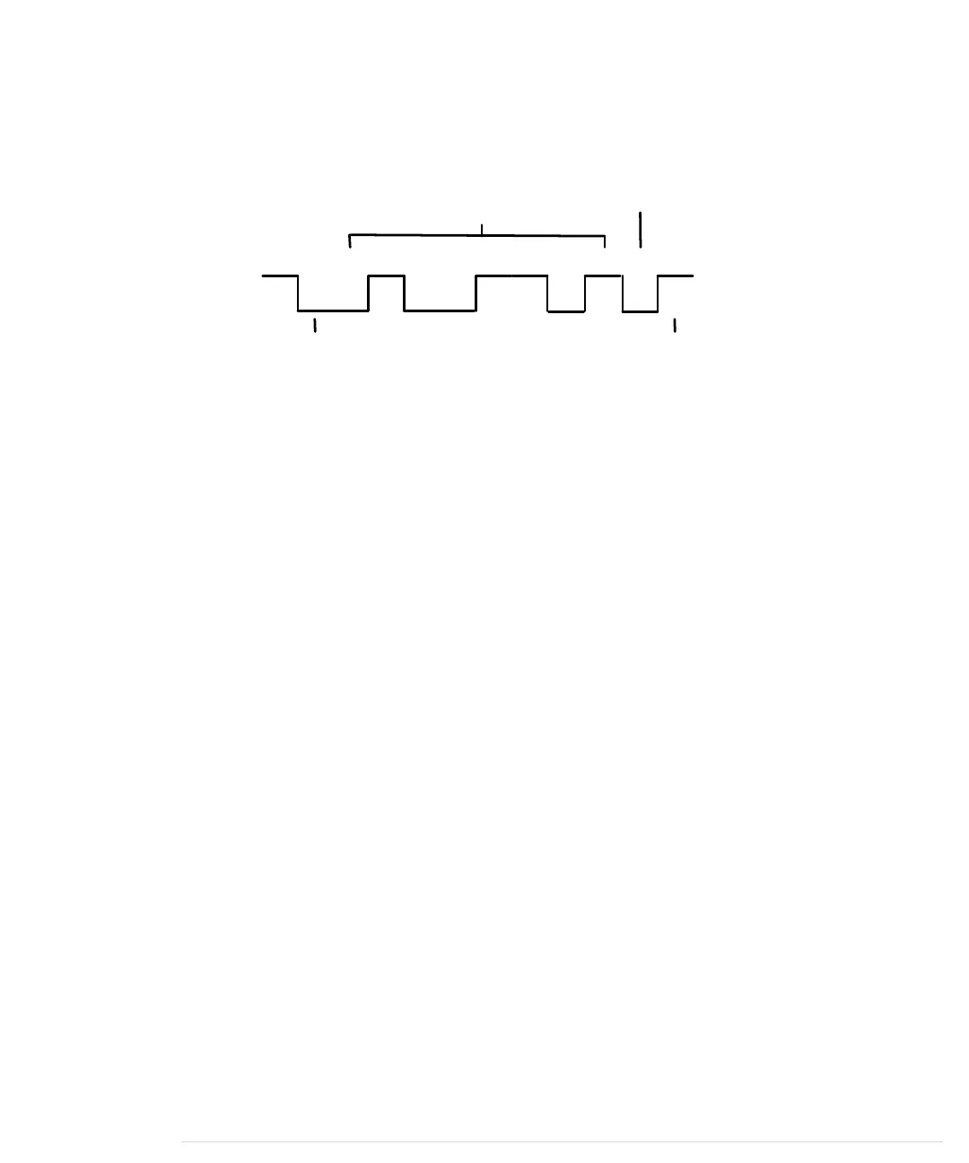
The following parameters control a serial communication:
0 1 00000 111 1
Start Bit
Parity
Stop Bit
Data
• A start bit indicates the beginning of a data word and is used to synchro-
nize the transmitter and receiver. It is always 0.
• A stop bit tells us when the last data bit has been sent and separates two
consecutive data words. Depending on the particular protocol agreement,
there can be more than one stop bit, but that happens rarely.
• Information is transferred as binary data bits; that is, if you’d like to
transmit the letter M, you have to turn it into a number first. Several
character set encodings are available, but when working with the Arduino,
the ASCII encoding fits best. In ASCII, an uppercase M is encoded as the
decimal number 77, which is 01001101 in binary. This is the bit sequence
that eventually gets transmitted.
• The parity bit indicates whether the number of 1s in the data has been
odd or even. This is a simple error-checking algorithm that is rarely used
and that stems from a time when network connections were less reliable
than they are today. Parity control can be “none” (no parity bit is sent),
“odd” (the parity bit is set if the amount of 1s in the data bits is odd;
otherwise, it is 0), or “even” (the parity bit is set if the amount of 1s in the
data bits is even; otherwise, it is 0). We chose odd parity for our data, and
because there are 4 bits set to 1 in 01001101, the parity bit is 0.
• The baud rate defines the transmission speed and is measured in trans-
mission steps per second. When working with the Arduino, typical baud
rates are 9600, 14400, 19200, or even 115200. Note that the baud rate
doesn’t define how much data is actually transferred per second, because
you have to take the control bits into account. If your connection settings
are 1 start bit, 1 stop bit, no parity, and 8 bits per byte, then you have to
transfer 1 + 1 + 8 = 10 bits to transfer a single byte. With a baud rate set
to 9600, you can then theoretically send 9600 / 10 = 960 bytes per sec-
ond—at least if every bit gets transferred in exactly one transmission step.
Appendix 3. Advanced Serial Programming • 254
report erratum • discuss
www.it-ebooks.info

Table of Contents

Other manuals for Arduino uno

Question and Answer IconNeed help?

Do you have a question about the Arduino uno and is the answer not in the manual?

Arduino uno Specifications

General IconGeneral
Form factorArduino
CertificationRoHS, FC, CE
Processor model-
Processor frequency- MHz
Microcontroller modelATmega328
Microcontroller frequency16 MHz
DC input voltage7-12 V
Operating voltage5 V
DC current per I/O pin40 mA
Flash memory0.032 MB
Maximum internal memory- GB
SRAM (Static Random Access Memory)2 KB
EEPROM (Electrically Erasable Programmable Read-Only Memory)1 KB
Wi-FiNo
Number of analog I/O pins6
Number of digital I/O pins14
Weight and Dimensions IconWeight and Dimensions
Board dimensions53.4 x 68.6 mm

Summary

Arduino Uno and the Arduino Platform

The Parts You Need

Chapter 1: Welcome to the Arduino

Installing the Arduino IDE

Provides step-by-step instructions for installing the Arduino Integrated Development Environment.

Hello, World!

Introduces the first project: making an LED blink using the Arduino.

Compiling and Uploading Programs

Explains how to compile and upload sketches to the Arduino board.

Chapter 2: Creating Bigger Projects with the Arduino

Changing Preferences

Explains how to customize Arduino IDE settings for better workflow.

Using Serial Ports

Explains serial communication for data exchange between Arduino and computer.

Chapter 3: Building Binary Dice

Working with Breadboards

Explains how breadboards work and how to connect components.

First Version of a Binary Die

Implements the first version of a binary die using three LEDs.

Working with Buttons

Details how pushbuttons work and how to connect them to the Arduino.

Building a Dice Game

Completes the dice project by adding a guess button and game logic.

Chapter 4: Building a Morse Code Generator Library

Building a Morse Code Generator

Starts the implementation of the Telegraph C++ class.

Fleshing Out the Morse Code Generator’s Interface

Defines the Telegraph class interface and Morse code data arrays.

Installing and Using the Telegraph Class

Guides on integrating the custom Telegraph library into Arduino IDE.

Chapter 5: Sensing the World Around Us

Measuring Distances with an Ultrasonic Sensor

Introduces ultrasonic sensors and builds a distance measuring device.

Increasing Precision Using a Temperature Sensor

Integrates a temperature sensor to refine distance measurements.

Chapter 6: Building a Motion-Sensing Game Controller

Wiring Up the Accelerometer

Details connecting the ADXL335 accelerometer to the Arduino.

Bringing Your Accelerometer to Life

Reads and outputs raw accelerometer data for three axes.

Building Your Own Game Controller

Integrates a pushbutton and refined accelerometer data for a game controller.

Chapter 7: Writing a Game for the Motion-Sensing Game Controller

Writing a GameController Class

Creates a JavaScript class for convenient access to Arduino motion data.

Creating the Game

Implements a Breakout clone using JavaScript and the motion controller.

Chapter 8: Generating Video Signals with an Arduino

Building a Digital-to-Analog Converter (DAC)

Details building a binary-weighted DAC for video signal generation.

Connecting the Arduino to Your TV Set

Describes modifying an RCA cable to connect to the Arduino.

Using the TVout Library

Introduces the TVout library for generating video signals on a TV.

Building a TV Thermometer

Creates a graphical thermometer display on a TV screen using sensors.

Chapter 9: Tinkering with the Wii Nunchuk

Wiring a Wii Nunchuk

Details wiring the Nunchuk controller to Arduino analog pins.

Building a Nunchuk Class

Creates a C++ class for interfacing with the Nunchuk controller.

Using Our Nunchuk Class

Demonstrates reading Nunchuk data (joystick, accelerometer, buttons).

Chapter 10: Networking with Arduino

Chapter 11: Creating a Burglar Alarm with Email Notification

Chapter 12: Creating Your Own Universal Remote Control

Chapter 13: Controlling Motors with Arduino

What You Need

Lists components for motor control: servo motor, wires, Arduino.

What If It Doesn’t Work?

Troubleshooting motor control: power consumption, weight, adjustments.

APPENDIX 1: Electronics and Soldering Basics

APPENDIX 2: Advanced Arduino Programming

APPENDIX 3: Advanced Serial Programming

APPENDIX 4: Controlling the Arduino with a Browser

Related product manuals