Functional Description
2-6 Copyright © 2008 ARM Limited. All rights reserved. ARM DDI 0414C
Non-Confidential
Restricted Access
Instruction tag, Data tag and SCU tag RAMs
Instruction tag RAMs, Data tag RAMs and SCU tag RAMs all consist of four arrays
per CPU. Data tag RAMs and SCU tag RAMs are identical in structure. Two arrays are
tested in parallel for each CPU.
Table 2-4 shows the MBISTARRAY bits used to select each tag RAM.
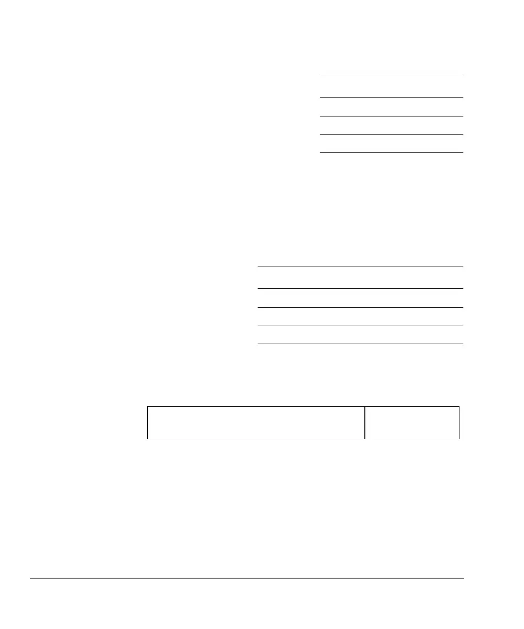
Figure 2-3 and Figure 2-4 on page 2-7 show the data mapping on MBISTINDATA and
MBISTOUTDATA buses for Instruction tag RAM.
Figure 2-3 Data in for Instruction tag RAM
1 Byte 1, bits [15:8]
2 Byte 2, bits [23:16]
3 Byte 3, bits [31:24]
Table 2-4 MBISTARRAY bit usage for tag RAMs
MBISTARRAY bits Description
[3:2] Select the Instruction tag array
[12:11] Select the Data tag array
[19:18] Select the SCU tag array
Table 2-3 Data data RAM byte write enable control (continued)
MBISTBE bit Description
MBISTINDATA[63:0]
Data in [21:0] for array n
Unused
3132 0525363 2122