Functional Description
2-18 Copyright © 2008 ARM Limited. All rights reserved. ARM DDI 0414C
Non-Confidential
Restricted Access
Table 2-9 shows the format of the data log.
The address contained in the data log refers to the full address of the failing location as
it appears on the MBISTADDR[10:0] port of the MBIST interface of the Cortex-A9
processor.
See also Chapter 4 MBIST Datalog Register.
2.2.2 Bitmap mode
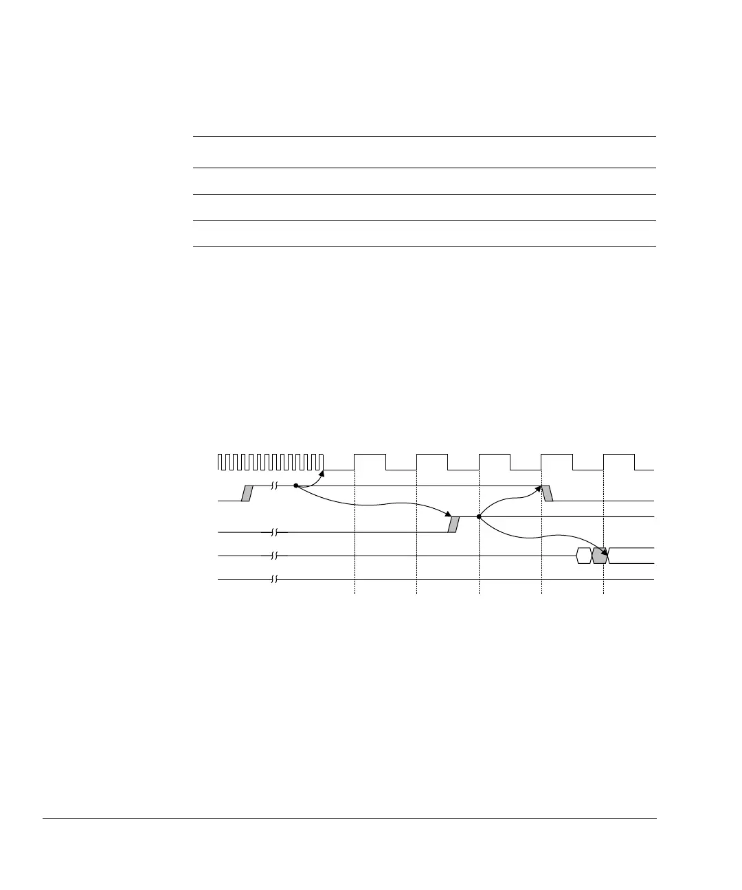
In bitmap mode, you can identify all failing locations in a RAM. Each time a failure
occurs, the controller stops executing the current test and waits for you to begin shifting
out the data log as Figure 2-20 shows.
Figure 2-20 Start of bitmap data log retrieval
After you finish shifting and drive MBISTDSHIFT LOW, the controller then resumes
testing where it stopped as Figure 2-21 on page 2-19 shows. This process continues
until the test algorithm completes. A fault can cause a failure to occur several times
during a given test algorithm. The fault might be logged multiple times depending on
the number of reads performed by the algorithm and the exact nature of the fault.
Table 2-9 Data log format
Bits Description
[78:68] Address of the failing location.
[67:4] Failing data bits. These bits are set for faulty bits and cleared for passing bits.
[3:0] The data seed used in the test. See DataWord field, MBIR[27:24] on page 3-11.
CLK
MBISTRESULT[1]
(fail flag)
MBISTDSHIFT
MBISTRESULT[5:2]
(data log shift out)
MBISTRUN
D[0]