Functional Description
ARM DDI 0414C Copyright © 2008 ARM Limited. All rights reserved. 2-15
Restricted Access Non-Confidential
2.2 Functional operation
The functional operation is described in:
• Timing
• Bitmap mode on page 2-18.
2.2.1 Timing
A 58-bit instruction, loaded serially at the start of each test, controls the operation of the
MBIST controller. Chapter 3 MBIST Instruction Register describes how to write the
instruction.
The timing diagrams in this section show the clock running at two different speeds:
• the slower clock relates to the clock driven by your ATE
• the faster clock relates to the clock driven by an on-chip Phase Locked Loop
(PLL).
If you do not have an on-chip PLL, both clocks relate to the clock driven by your ATE.
Timing diagrams in the following sections show the procedures for operating the
MBIST controller:
• Instruction load
• Starting MBIST on page 2-16
• Failure detection on page 2-16
• Data log retrieval on page 2-16.
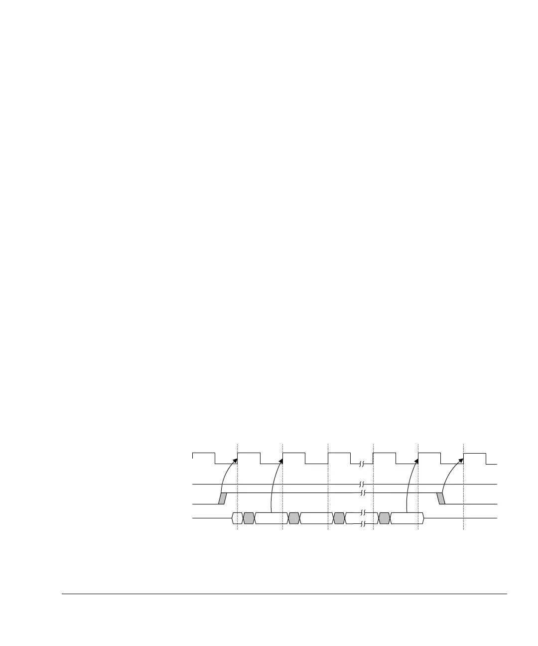
Instruction load
To load an MBIST instruction, drive MBISTSHIFT HIGH. At the next rising clock
edge, the 58-bit shift sequence begins as shown in Figure 2-15. To enable data input
from the ATE, the PLL is in bypass mode, and the clock is not running at test frequency.
Figure 2-15 Loading the MBIST controller instruction
i[0] i[1] i[57]
CLK
MBISTRUN
MBISTSHIFT
MBISTDATAIN