Functional Description
ARM DDI 0414C Copyright © 2008 ARM Limited. All rights reserved. 2-11
Restricted Access Non-Confidential
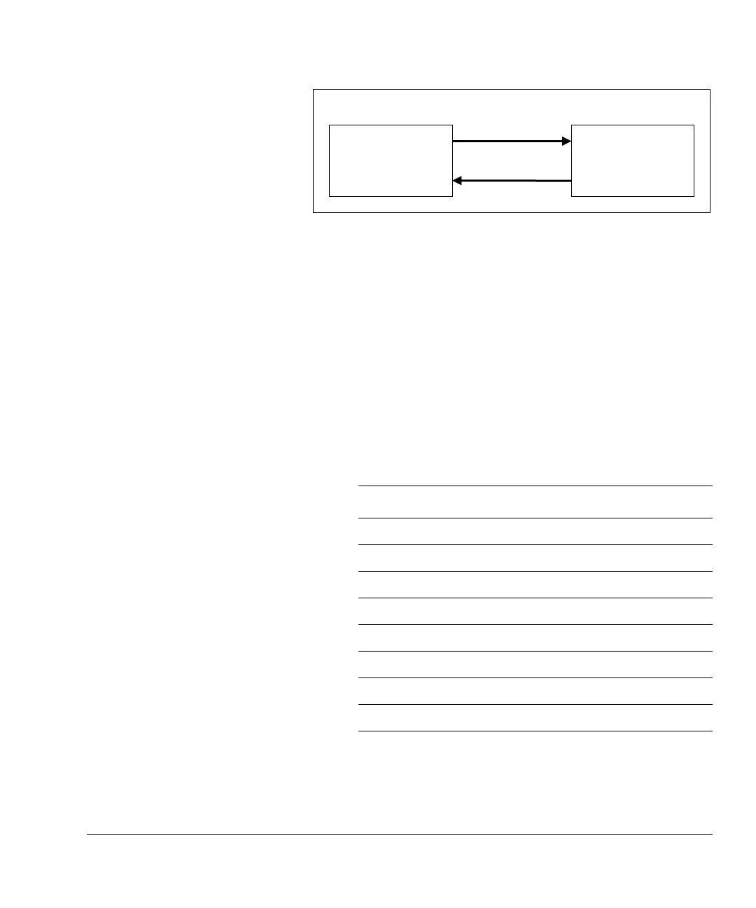
Figure 2-14 MBIST controller block
This section describes:
• MBIST controller and dispatch unit interface
• MBIST controller block top level I/O on page 2-13.
MBIST controller and dispatch unit interface
The MBIST controller and the dispatch unit communicate using the following signals:
MBISTTX[11:0]
This signal is an output of the MBIST controller that goes to the dispatch
unit. Table 2-6 shows the signals.
MBIST controller Dispatch unit
MBIST controller block
MBISTTX[11:0]
MBISTRX[5:0]
Table 2-6 MBISTTX signals
MBISTTX bit Description
0 Reset address
1 Increment address
2 Access sacrificial row, used during bang patterns
3 Invert data/instruction data in
4 Checkerboard data
5 Write data
6 Read data
7 Yfast/nXfast
8Direction