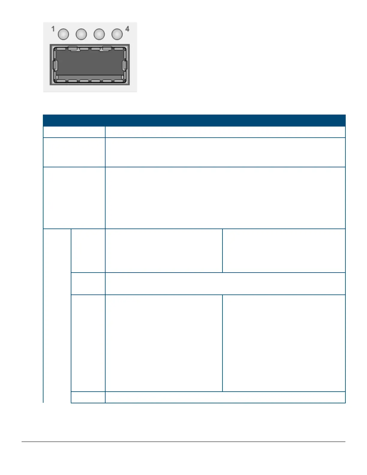
Table 15: Uplink module LEDs
40GbE mode 4x10GbE mode
Power-on / reset All four LEDs cycle through Green-Orange-Green-Off
Self-test
During boot, all four LEDs will flicker green, then clear.
During a failure, all four LEDs slow-blink orange synchronously with the Chassis Fault
LED, Management Module Test, and module number LEDs.
QSFP+ device ID
and authentication
All four LEDs turn on green for ~two seconds when QSFP+ device passes ID and
authentication.
All four LEDs slow-blink orange when QSFP+ device fails identification (unsupported
device).
All four LEDs slow-blink orange synchronously with the Chassis Fault LED and
Management Module Test and Module Number LEDs when QSFP+ device fails
authentication.
LED
mode
Activity
All four LEDs flicker green synchronously
to indicate traffic on the 40G link.
Off = Linked but no traffic, no link, or
device not installed.
Individual LEDs flicker green
asynchronously to indicate traffic on each
active 10G links.
Off = Linked but no traffic, no link, or device
not installed.
Duplex
All four LEDs turn on green to indicate full-duplex.
All four LEDs clear when there is no link or QSFP+ device is not installed.
Speed
QSFP+ device installed:
• All four LEDs turn on green to indicate
port configured for 40GbE mode and
linked.
• LEDs off to indicate that port is not
linked.
QSFP+ device not installed:
All four LEDs on green indicates port
configured for 40GbE mode.
QSFP+ device installed:
• All four LEDs slow-blink green to indicate
that port is configured for 4x10GbE mode
and linked.
• LEDs off to indicate that port is not
linked.
QSFP+ device not installed:
All four LEDs slow-blink green to indicate
that port is configured for 4x10GbE mode.
PoE Off
Table Continued
Chapter 2 Introducing the 2930M switches 29




 To Next Page