Looking at any member, you can see that there are four members defined in the stack configuration, with member
numbers 1, 2, 3, and 5 because these are the LEDs that are lit. The port 4 LED is off, indicating that this member
number is not defined in the stack.
On all members, Port 1 LED is fast flashing, indicating that member 1 is the commander of the stack. Port 3 LED
is on orange, indicating either that 3 is rebooting or not communicating because of an unknown fault.
When looking at member 1, only Port 1 LED is fast flashing green. This behavior indicates that this unit is member
1 and is the commander.
When looking at member 2, the port 2 LED is slow flashing green, indicating that unit is member number 2.
Likewise on member 5, the port 5 LED is slow flashing green, indicating that unit is member 5.
Member 3 will be going through the normal boot LED boot up sequence. When it has completed booting and
joined the stack, if you exit and re-enter USER mode, the members show the following on their port LEDs:
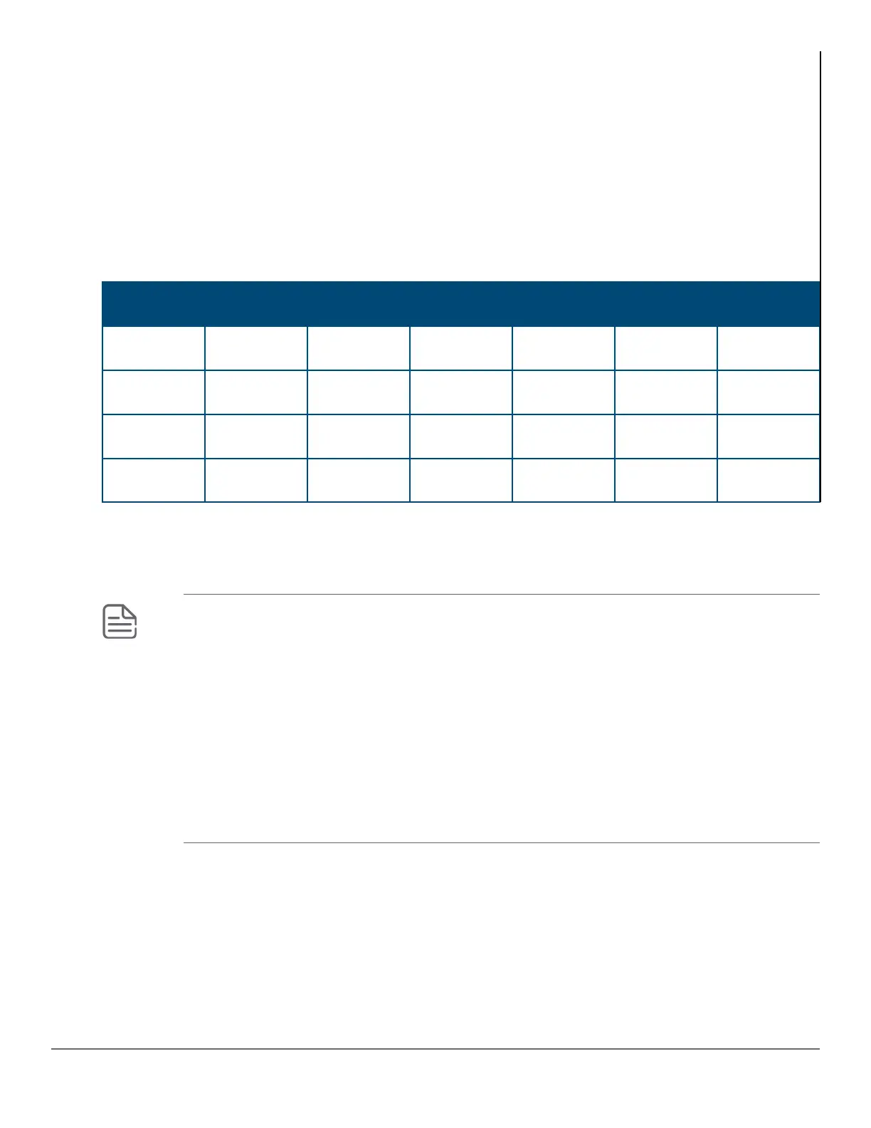
Port 1 LED Port 2 LED Port 3 LED Port 4 LED Port 5 LED Port 6-10
LEDs
Member 1 Fast Flash
Green
On Green On Green Off On Green Off
Member 2 Fast Flash
Green
Slow Flash
Green
On Green Off On Green Off
Member 3 Fast Flash
Green
On Green Slow Flash
Green
Off On Green Off
Member 5 Fast Flash
Green
On Green On Green Off Slow Flash
Green
Off
LED mode select button and indicator LEDs
The state of the mode LEDs is controlled by the LED Mode select button. The current view mode is indicated by
the mode LEDs next to the button. To step from one view mode to the next, press the button.
NOTE: Stacking Notes
• For 2930M switches that are in a stack, the LED Mode select button on every switch in the stack
controls the LED mode for all the switches in the stack. Using the LED Mode select button on one
switch in the stack changes the LED mode for the entire stack.
• If there is a combination of PoE switches and non-PoE switches in the stack, when any LED
Mode select buttons is pressed to put the stack into PoE mode, the non-PoE switches indicate no
PoE support by not illuminating any of the mode indicator LEDs or any of the port LEDs.
• If any of the switches in the stack are configured with the Save Power LED feature, the default
LED mode for the whole stack becomes the Save Power display. (This condition means all LED
mode indicator LEDs are off). However, only the stack members on which that feature is
configured display the other characteristics of that feature (all LEDs off except for the power LED).
Reset and Clear buttons
The Reset and Clear buttons are recessed from the front panel (to protect them from being pushed accidentally)
and are accessible through small holes on the top of the front panel. Use pointed objects, such as unbent paper
clips, to push them.
The buttons are used singly or in combination, as follows:
20 Aruba 2930M Switches




 To Next Page