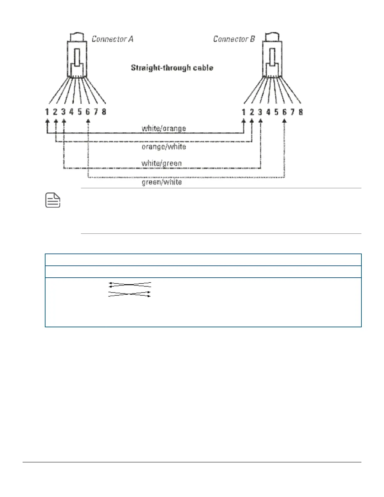
Cable diagram
NOTE: Pins 1 and 2 on connector “A” must be wired as a twisted pair to pins 1 and 2 on connector
“B”.
Pins 3 and 6 on connector “A” must be wired as a twisted pair to pins 3 and 6 on connector “B”.
Pins 4, 5, 7, and 8 are not used in this application, although they may be wired in the cable.
Pin assignments
Switch end (MDI-X) Hub or switch port, or other MDI-X port end
Signal Pins Pins Signal
receive +
receive -
transmit +
transmit -
1
2
3
6
6
3
2
1
transmit -
transmit +
receive -
receive +
Straight-through twisted-pair cable for 1000 Mbps network connections
1000Base-T connections require that all four pairs or wires be connected.
Chapter 8 Cabling and technology information 95