53
2467S–AVR–07/09
ATmega128
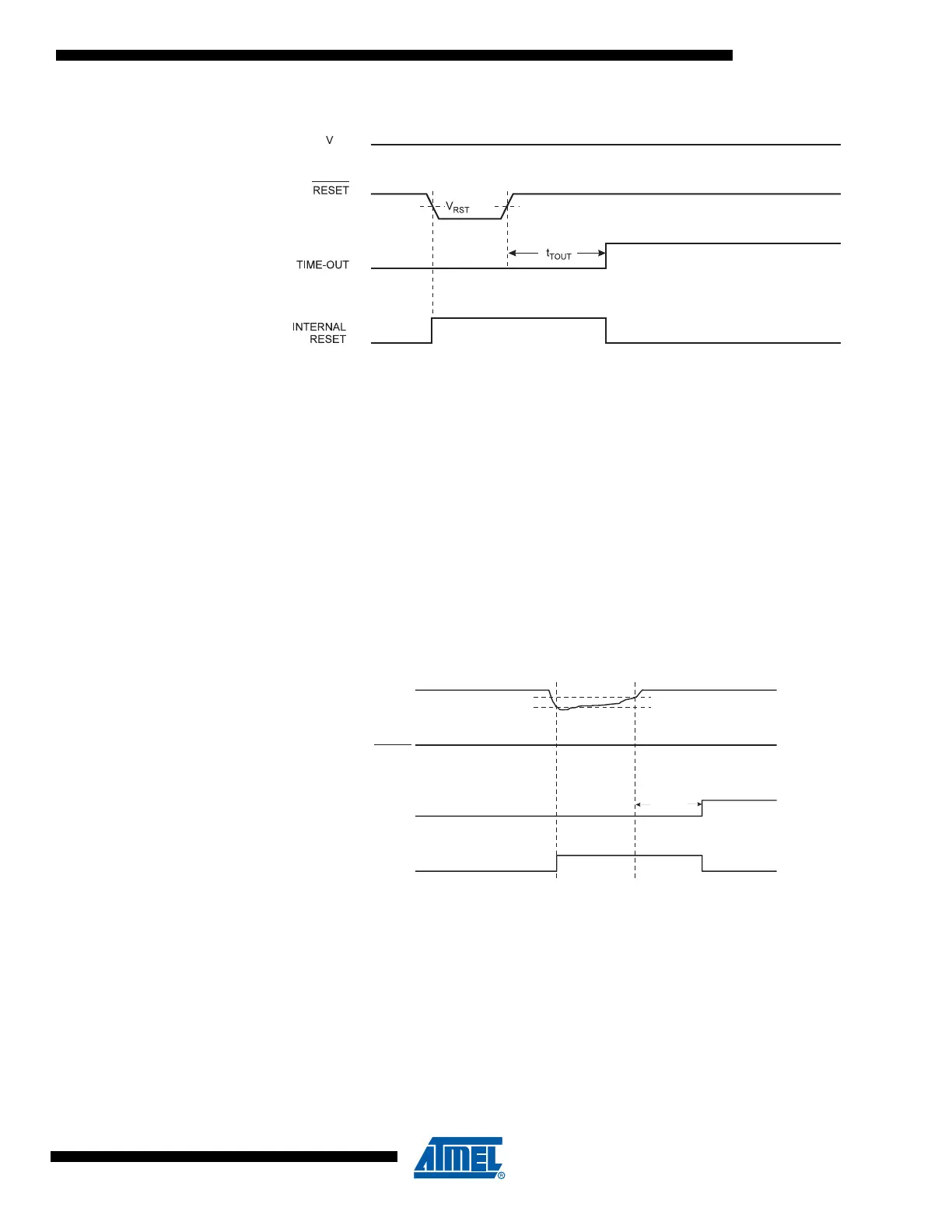
Figure 25. External Reset During Operation
Brown-out Detection ATmega128 has an On-chip Brown-out Detection (BOD) circuit for monitoring the V
CC
level dur-
ing operation by comparing it to a fixed trigger level. The trigger level for the BOD can be
selected by the fuse BODLEVEL to be 2.7V (BODLEVEL unprogrammed), or 4.0V (BODLEVEL
programmed). The trigger level has a hysteresis to ensure spike free Brown-out Detection. The
hysteresis on the detection level should be interpreted as V
BOT+
= V
BOT
+ V
HYST
/2 and V
BOT-
=
V
BOT
- V
HYST
/2.
The BOD circuit can be enabled/disabled by the fuse BODEN. When the BOD is enabled
(BODEN programmed), and V
CC
decreases to a value below the trigger level (V
BOT-
in Figure
26), the Brown-out Reset is immediately activated. When V
CC
increases above the trigger level
(V
BOT+
in Figure 26), the delay counter starts the MCU after the time-out period t
TOUT
has
expired.
The BOD circuit will only detect a drop in V
CC
if the voltage stays below the trigger level for lon-
ger than t
BOD
given in Table 19.
Figure 26. Brown-out Reset During Operation
V
CC
RESET
TIME-OUT
INTERNAL
RESET
V
BOT-
V
BOT+
t
TOUT