103
2467S–AVR–07/09
ATmega128
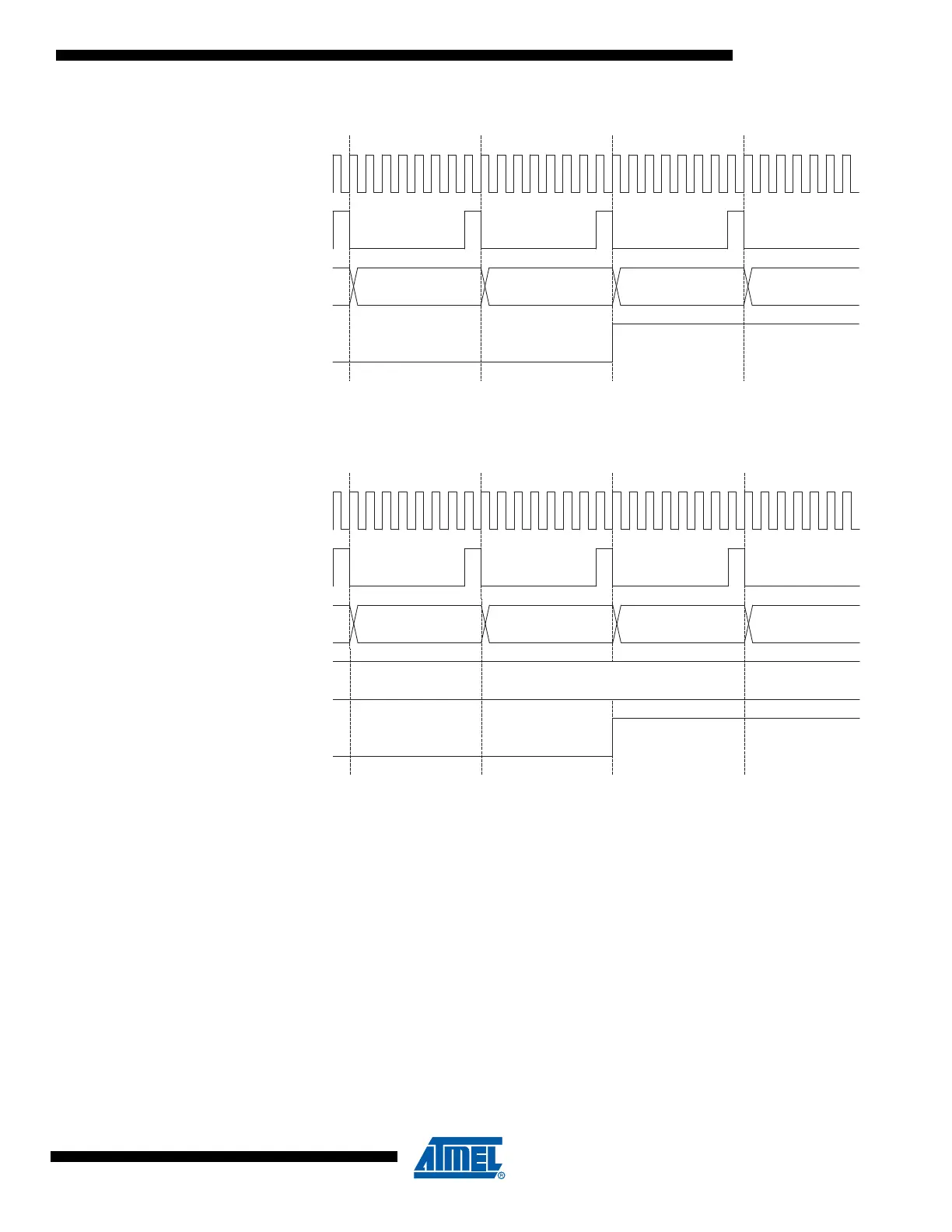
Figure 42. Timer/Counter Timing Diagram, with Prescaler (f
clk_I/O
/8)
Figure 43 shows the setting of OCF0 in all modes except CTC mode.
Figure 43. Timer/Counter Timing Diagram, Setting of OCF0, with Prescaler (f
clk_I/O
/8)
Figure 44 shows the setting of OCF0 and the clearing of TCNT0 in CTC mode.
TOVn
TCNTn
MAX - 1 MAX BOTTOM BOTTOM + 1
clk
I/O
clk
Tn
(clk
I/O
/8)
OCFn
OCRn
TCNTn
OCRn Value
OCRn - 1 OCRn OCRn + 1 OCRn + 2
clk
I/O
clk
Tn
(clk
I/O
/8)