41
2467S–AVR–07/09
ATmega128
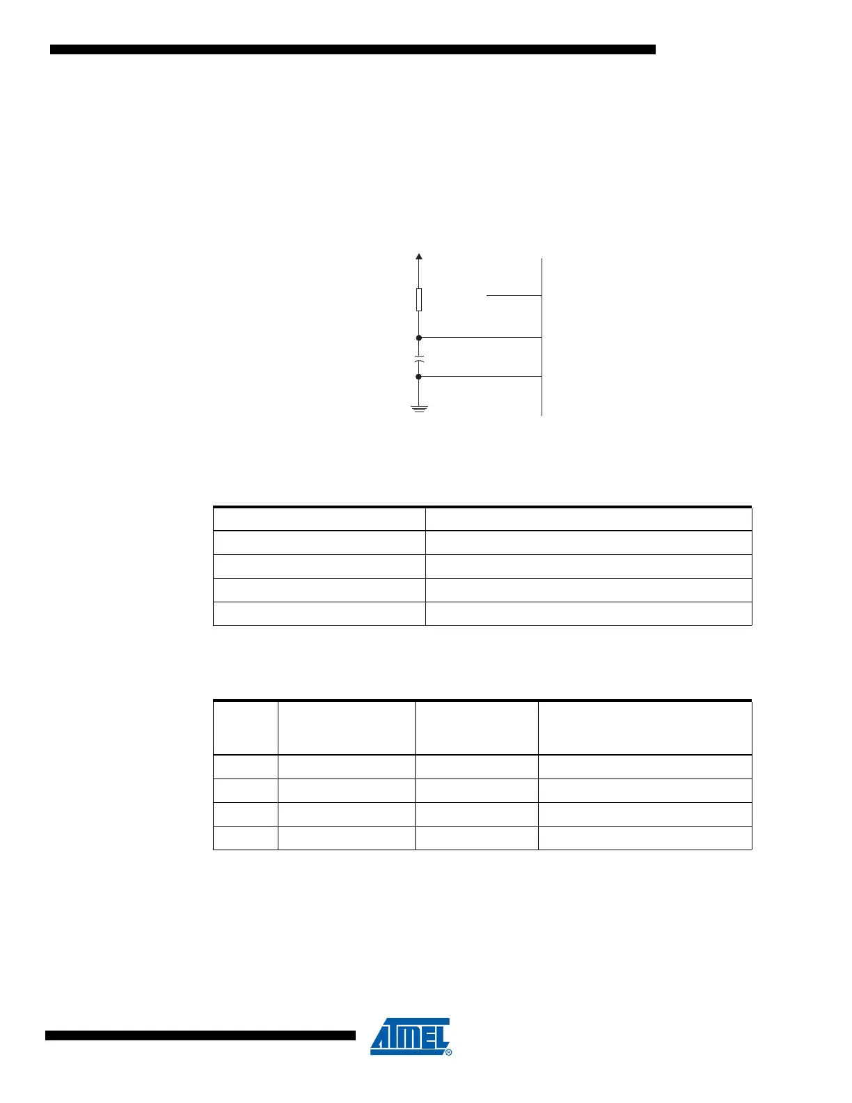
External RC
Oscillator
For timing insensitive applications, the External RC configuration shown in Figure 20 can be
used. The frequency is roughly estimated by the equation f = 1/(3RC). C should be at least 22
pF. By programming the CKOPT fuse, the user can enable an internal 36 pF capacitor between
XTAL1 and GND, thereby removing the need for an external capacitor. For more information on
Oscillator operation and details on how to choose R and C, refer to the External RC Oscillator
application note.
Figure 20. External RC Configuration
The Oscillator can operate in four different modes, each optimized for a specific frequency
range. The operating mode is selected by the fuses CKSEL3..0 as shown in Table 11.
When this Oscillator is selected, start-up times are determined by the SUT fuses as shown in
Table 12.
Note: 1. This option should not be used when operating close to the maximum frequency of the device.
Table 11. External RC Oscillator Operating Modes
CKSEL3..0 Frequency Range (MHz)
0101 0.1 - 0.9
0110 0.9 - 3.0
0111 3.0 - 8.0
1000 8.0 - 12.0
Table 12. Start-Up Times for the External RC Oscillator Clock Selection
SUT1..0
Start-up Time from
Power-down and
Power-save
Additional Delay
from Reset
(V
CC
= 5.0V) Recommended Usage
00 18 CK – BOD enabled
01 18 CK 4.1 ms Fast rising power
10 18 CK 65 ms Slowly rising power
11 6 CK
(1)
4.1 ms Fast rising power or BOD enabled